Pipework connections
Compress 5800i AW – 6721862724 (2023/06)
12
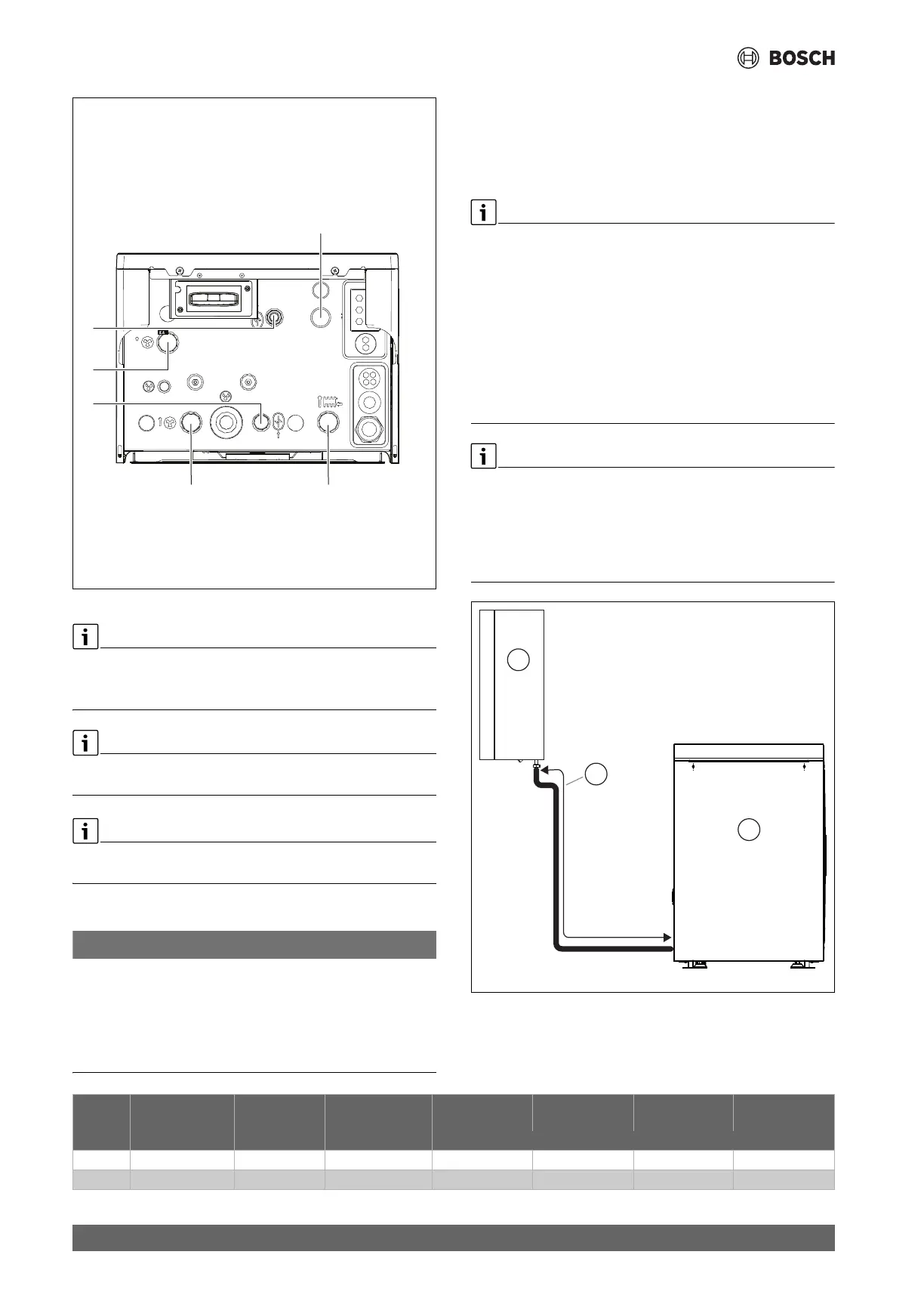
Fig. 14 Pipe connections
If Installation is done without a DHW cylinder, the pipes need to be
capped.
▶ Put caps on the flow- and return DHW pipes.
If no DHW cylinder is connected, then the backup electric heater needs
to be activated to ensure active defrost.
In accordance with good installer practice it may be required to install
additional air vent valves at the highest point of installation.
5.1 Insulation
NOTICE
Material damage from frost!
In case of a power outage the water in the pipes may freeze.
▶ Use insulation with a thickness of at least 19 mm for pipework
outdoors.
▶ In buildings, use insulation with a thickness of at least 12 mm for
pipework. This is also important for safe and efficient DHW mode.
All heat-conducting pipework must be provided with suitable thermal
insulation according to applicable regulations.
In cooling mode, all connections and lines must be insulated according to
applicable standards to prevent condensation.
5.2 Pipe connections, general
Dimension the pipes according to the instructions (table 7).
▶ Avoid pipe joints in the heat transfer pipes to minimise pressure
drop.
▶ Use PEX pipes for all connections between the heat pump and indoor
unit.
▶ Use only material (pipes and connections) from the same PEX
distributor to avoid leakage.
▶ Pre-insulated AluPEX pipes are recommended since they make
installation easier and prevent gaps in the insulation. PEX or AluPEX
pipes also devibrate and insulate against noise transfer to the heating
system.
If a different material than PEX is used, the following is required:
▶ Install a particulate filter intended for outdoor use on the heat pump
return line, directly on the heat exchanger.
▶ Insulate the particle filter as other connections.
▶ Devibrate the heat pump connection with a hose intended for outside
use and insulate it.
Fig. 15 Pipe length A
[1] Indoor unit, wall-mounted
[2] Heat Pump
5.
3.
1.
4.
2.
6.
0010050410-001
1
2
A
0010039880-001
Heat
Pump
Heat transfer
fluid delta (K)
1)
Nominal flow
(L/min)
p (mbar)
2)
AX20 inner Ø 15
(mm)
AX25 inner Ø 18
(mm)
AX32 inner Ø 26
(mm)
AX40 inner Ø 33
(mm)
Maximum pipe length [A, Figure 15] PEX (m)
44 15
3)
437 9 23 30
5 5 17,3 376 5 15 30