Technical information and reports
Compress 5800i AW – 6721862724 (2023/06)
40
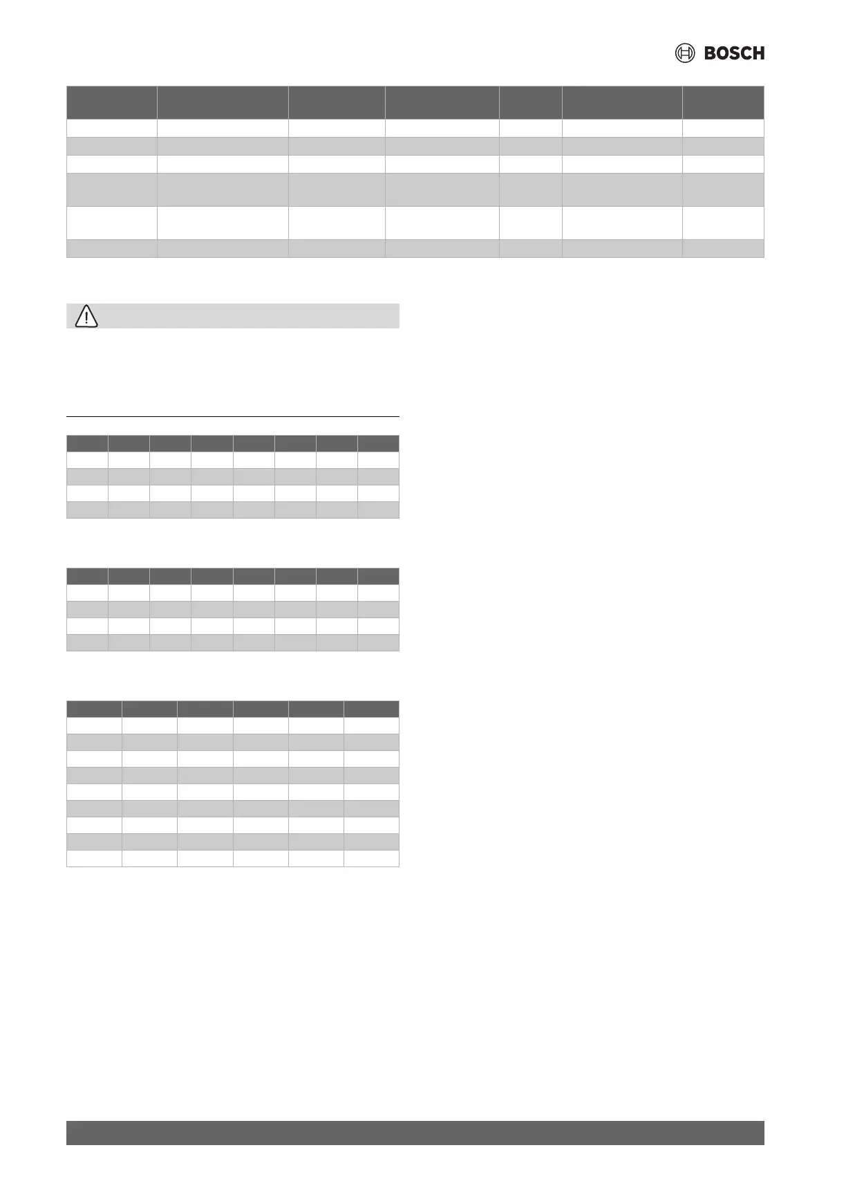
Table 17 Cable plan for sensors and bus cables
10.3.4 Measurements from temperature sensors
CAUTION
Physical injury or material damage due to incorrect temperature
If sensors with incorrect characteristics are used, the temperatures may
be too high or too low.
▶ Make sure that the temperature sensors used comply with the
specified values (see tables below).
Table 18 Sensor T0, TC0, TC1, TW1, TW2
This table applies if both TW1 and TW2 are connected.
Table 19 Sensor TW1
This table applies if only TW1 is connected.
Table 20 Sensor T1
TW1 Temperature sensor DHW 0,75 mm
2
LiYY 2 x 0,75 TW1: 1 / 2
TW2 Temperature sensor DHW 0,75 mm
2
LiYY 2 x 0,75 TW2: 1 / 2
MD1 Condensation sensor 0,5 mm
2
LiYY 2 x 0,5 MD1: 1 / 2
CAN-BUS Communication line: IDU -
ODU
0,75 mm
2
LiYCY (TP) 2 x 2 x 0,75
shielded
30 CAN BUS:
1 / 2 / 3 / 4
EMS-BUS EMS-BUS: Accessory 0,5 mm² LiYY 2 x 0,5
LiYCY 2 x 0,5 shielded
PWR BUS: EMS+ / EMS-
Smart Grid 0,5 mm² LiYY 2 x 0,5 I16: 1 / 2
Sensor/Bus General Minimum cross
section
Cable type Maximum
length (m)
Connection to XCU-
THH (XCU HY) pin
Power supply
°C °C °C °C
20 12500 40 5323 60 2489 80 1259
25 9999 45 4366 65 2085 85 1073
30 8053 50 3601 70 1754 90 918.7
35 6527 55 2986 75 1483 - -
°C °C °C °C
20 14768 40 6650 60 3242 80 1703
25 11977 45 5521 65 2744 85 1463
30 9783 50 4606 70 2332 90 1262
35 8045 55 3855 75 1989 - -
°C °C °C
– 40 162100 5 12000 50 1686
– 35 116600 10 9393 55 1398
– 30 84840 15 7405 60 1165
– 25 62370 20 5879 65 975.3
– 20 46320 25 4700 70 820.7
– 15 34740 30 3782 75 693.9
– 10 26290 35 3063 80 589.4
– 5 20080 40 2496 85 502.9
0 15460 45 2046 90 430.8
 Loading...


