Electrical connection
Compress 5800i AW – 6721862724 (2023/06)
18
HMalfunctions caused by electrical interference!
High-voltage cables (230/400 V) in the vicinity of communication- and
sensor cables can cause the indoor unit to malfunction.
▶ Route communication- and sensor cables with a minimum distance of
100 mm separately to power cables. The communication cable can
be routed together with sensor cables.
6.2 General information
▶ Observe protective measures according to national and international
regulations.
▶ Do not connect any other consumers to the mains connection of the
device.
▶ Provide fuses according to the specifications:
three-phase mains power supply (400 V) for booster heater stage
9kW Section 6.10.1
one-phase mains power supply (230 V) for booster heater stages
3kW and 6kW Section 6.10.1.
▶ Select cable diameter and type according to fuse size and wiring
type.
▶ Connect the indoor unit according to the wiring diagram. Do not
connect any other consumers.
▶ Always connect the three-phase indoor unit directly to the main
distribution board via a three-pole automatic circuit breaker.
▶ Pay attention to the color coding when replacing circuit boards.
It must be possible to safely interrupt the power supply to the device.
▶ Install a separate safety switch that completely de-energizes the
indoor unit. When the power supply is separate, a separate safety
switch is needed for each supply line.
▶ Select the appropriate conductor cross-sections and cable types for
the respective fuse protection and routing method.
▶ Connect the unit according to the chapters 6.10.4 – 6.10.6. No
additional consumers may be connected.
When extending temperature sensor cables, use the conductor
diameters given in the cable plan ( Chapter 10.3.3).
6.3 CAN-BUS
NOTICE
The system will be damaged if the 24VDC- and the CAN-BUS
connections are incorrectly connected!
The communication circuits are not designed for 24VDC constant
voltage.
▶ Check to ensure that the cables are connected to the contacts with
the corresponding markings on the modules.
NOTICE
Malfunction due to mixed up connections!
If the “High” (H) and “Low” (L) connections are mixed up, there is no
communication between the heat pump and the indoor unit.
▶ Check to ensure that the cables are connected to the connections
with the corresponding markings in both ends of the CAN-BUS cable.
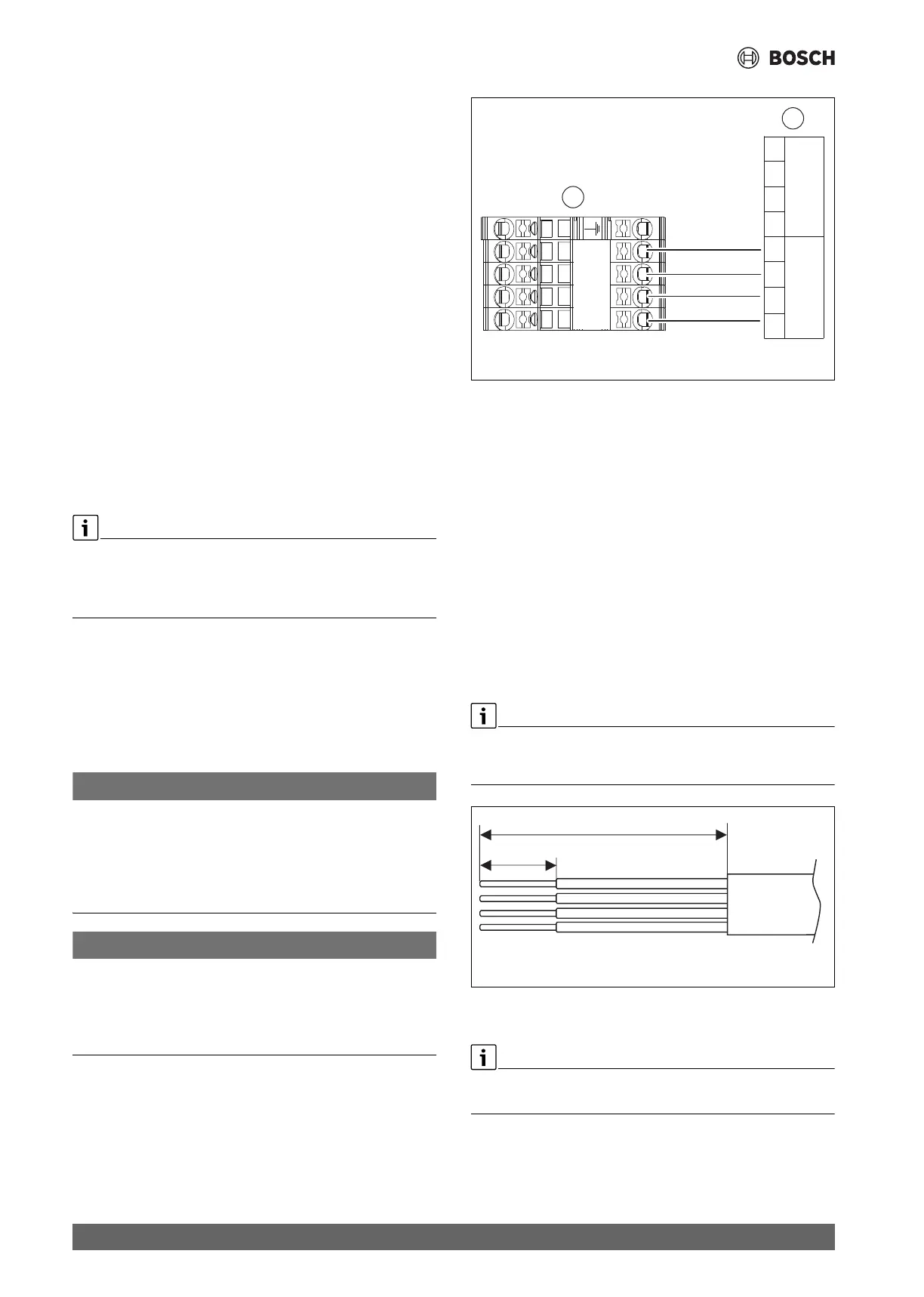
Fig. 20 CAN-BUS heat pump - indoor unit
[A] Heat pump
[B] Indoor unit
[Vcc] 24V= (24VDC)
[H] HIGH
[L] LOW
[GND] gnd
The heat pump and indoor unit are connected to each other by a
communication line, the CAN-BUS [24VDC, class III (SELV)].
A LIYCY cable (TP) 2 x 2 x 0.75 (or equivalent) is suitable as an
extension cable outside of the unit. Alternatively, twisted pair cables
approved for outdoor use with a minimum cross-section of 0.75 mm
2
can be used.
The maximum permissible cable length is 30 m.
The connection is made with four wires, as the 24VDC supply is also
connected. The 24VDC and CAN-BUS connections are marked on the
module.
The CANBUS cable has two pairs of twisted wires. Vcc and GND is one
pair, H and L is the second pair. Maximum cable insulation striping length
for all cables is 120mm. Maximum wire striping is between 8-10mm.
Fig. 21 Wire striping CAN-BUS
6.4 EMS-BUS for accessories
EMS-BUS and CAN-BUS are not compatible.
▶ Do not connect EMS-BUS units to CAN-BUS units.
The following applies to accessories that are connected to the EMS-BUS
[15VDC, class III (SELV)] (see also the installation instructions for the
respective accessories):
B
GND
L
H
Vcc
Vcc
L
H
GND
HIGH
LOW
gnd
CAN BUS
12
34
HIGH
LOW
gnd
CAN BUS
12
34
24V=
A
0010049010-001
≤10 mm
≤120 mm
0010041915-001