Electrical connection
17
Compress 5800i AW – 6721862724 (2023/06)
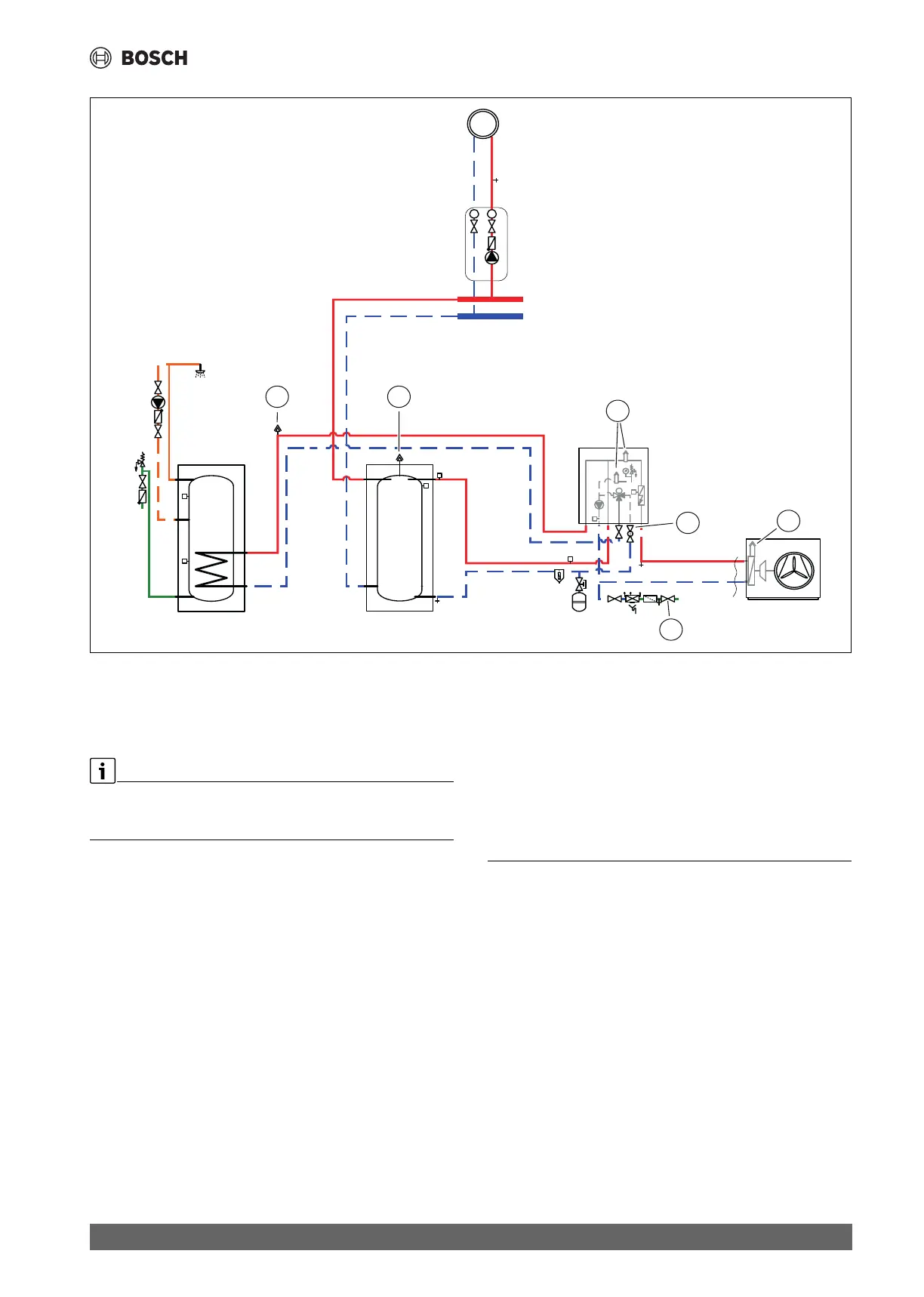
Fig. 19 Indoor unit, heat pump, DHW cylinder and heating system with buffer
[1] Automatic purge valve
[2] Manual purge valve
[3] Particle filter SC1
[4] Fill valve VW2
This filling procedure is valid for all systems, also where the heat pump is
placed above the indoor unit. For a less complex system the procedure
may be simplified.
Step 1: Filling the heat pump and the DHW cylinder
1. Switch off the power to the heat pump and the indoor unit.
2. Ensure that all temperature regulation valves in the heating system
are fully open.
3. Close the valves to the heating system VC3 and particle filter SC1 and
the valve to the DHW cylinder coil VC4.
4. Connect a hose to the drain valve VA0 and the other end to an outlet.
Open the valve.
5. Open the fill valve VW2 to fill the heat pump.
6. Continue filling until only water comes out of the drain hose and there
are no more bubbles in the heat pump.
7. Close the drain valve VA0 and the fill valve VW2.
8. Open the cold water valve VW3.
9. Open a hot water tap to fill the DHW cylinder. Close the tap when only
water is emerging.
Step 2: Filling the heating system
10.Move the drain hose to the heating system drain valve VC2.
11.Open the particle filter SC1, the valve to the DHW cylinder coil VC4,
the drain valve VC2 and the fill valve VW2 to fill the heating system.
12.Continue filling until only water comes out of the drain hose and there
are no more bubbles in the heating system.
13.Open the valve VC3.
14.Close the drain valve VC2 and remove the hose.
15.Open the manual air vent valves and close them when only water is
emerging.
16.Continue filling until target pressure ( table 11) is displayed at the
GC1 pressure gauge.
17.Close the fill valve VW2.
6 Electrical connection
6.1 Safety instructions
HDanger to life from electric shock
Means to safely disconnect the unit from supply mains must be
incorporated.
▶ Install a safety switch that disconnects all poles from supply mains.
The safety switch shall be an over voltage category III appliance.
▶ If there are several main connections, provide a safety switch of over
voltage category III for each connection.
HDanger to life from electric shock!
Touching live parts can lead to electric shock.
▶ Before working on any electrical part, interrupt all poles of the power
supply (230 V AC and 400 V 3P) to the indoor unit (by fuse or circuit
breaker).
▶ Secure against unintentional switching on again.
▶ Check that there is no voltage.
0010040384-005
PC0
PW2
PC1
T
T
VC3
VC2
VW3
VL1
SC1
VA0
VW2
VC4
MD1
T0
2
4
2
3
1
VL1
1