Technical information and reports
37
Compress 5800i AW – 6721862724 (2023/06)
10.3 Wiring diagram
10.3.1 Wiring diagram XCU-THH (XCU HY)
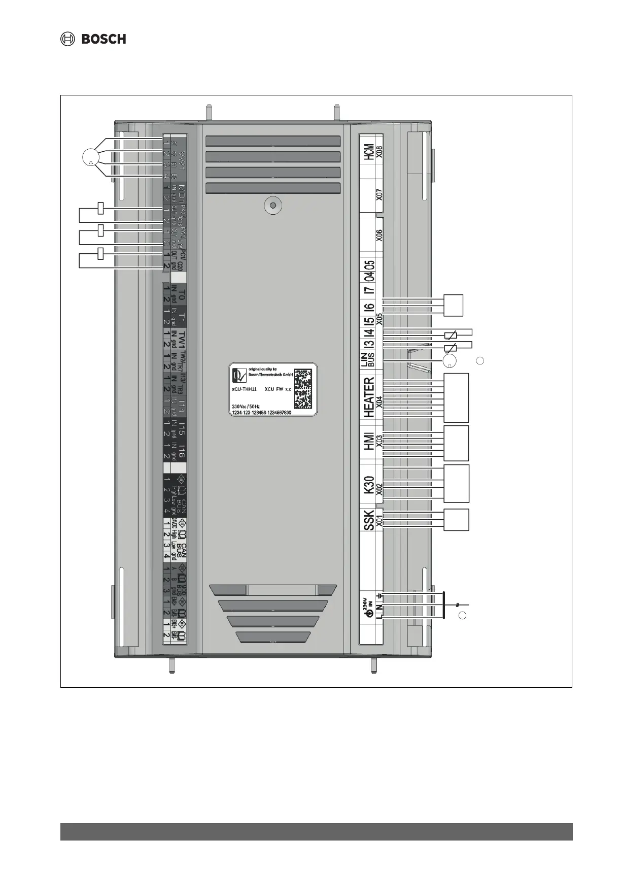
Fig. 40 Wiring diagram XCU-THH (XCU HY)
[SK] Service key
[K30] Connect-Key K30RF
[HMI] Control unit UI800
[TC0] Temperature sensor, heat transfer medium return
[TC1] Temperature sensor, heat transfer medium flow
[JC0] Pressure sensor
[Q4] Contactor for circulation pump, heating circuit (PC1)
[Q5] Contactor for DHW circulation pump (PW2)
[Q6] Contactor for circulation pump, cooling circuit (PK2)
[VW1] 3-way valve
[1] 230V~1N supply to XCU-THH (XCU HY)
[2] LIN-Bus to circulation pump (PC0)
0010039109-004
Q4
A2
Q5
A2
Q6
A2
VW1
MM
ϑϑ
TC0
ϑϑ
TC1
P
JC0
HMI
SK
Supply
1
K30
Heater
2
PC0
MM
A1
A1
A1
 Loading...


