Applications Manual FHP560 Controller | 11
Bosch Thermotechnology Corp.
Data subject to changePage____ of ____
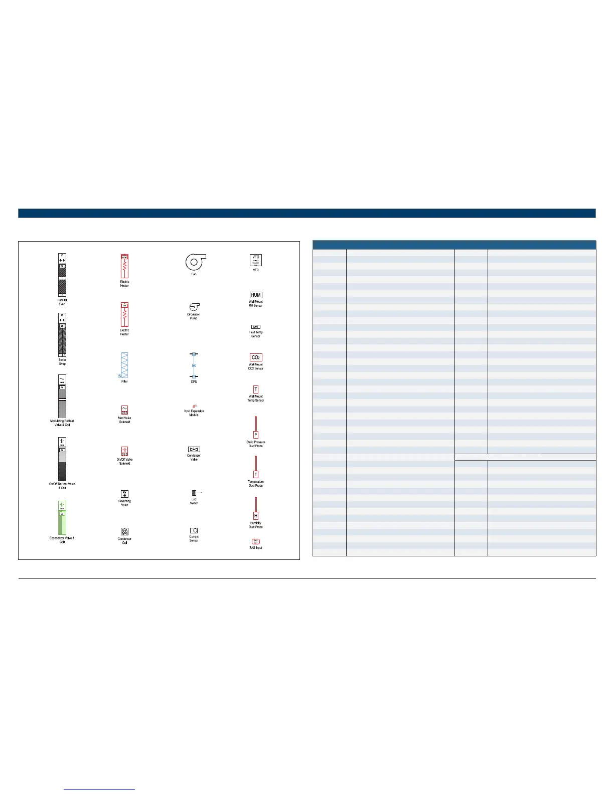
10 Symbol Legend
10.1 Common Abbreviations
Abbreviations
AFMS Air Flow Measuring Station MOD Modulating
AC Air Conditioning NC Normally Closed
ACU Air Conditioning Unit NO Normally Open
AHU Air Handling Unit OA Outdoor Air
AI Analog Input OAD Outdoor Air Damper
AO Analog Output OCC Occupancy
AUTO Automatic RA Return Air
AUX Auxiliary RF Return Fan
BAS Building Automation System RH Relative Humidity
BC Boilerless Control RV Reversing Valve
BI Binary Input SA Supply Air
BMS Building Management System SCR Silicon-Controlled Rectifi er
BO Binary Output SDP Secondary Drain Pan
C Common (24VAC) SDS Smoke Detector Switch
CHW Chilled Water SECS Seconds
COND Condenser SF Supply Fan
COMP Compressor SOO Sequence of Operation
CW Condenser Water SP Static Pressure
CWP Circulating Water Pump S/S Start/Stop
DA Discharge Air STG Stage
DDC Direct Digital Control TEMP Temperature
DES Damper End Switch UI Universal Input
DFS Dirty Filter Switch UPM Unit Protection Module
DI Digital Input VAV Variable Air Volume
DO Digital Output VES Valve End Switch
DPS Differential Pressure Switch VFD Variable Frequency Drive
DX Direct Expansion VLV Valve
EA Exhaust Air WSE Water-Side Economizer
EF Exhaust Fan WSHP Water Source Heat Pump
EVAP Evaporator
EW Entering Water THERMOSTAT SIGNALS
F Fahrenheit G Fan Signal
FM Flow Meter O Reversing Valve Signal
FSS Fan Status Switch Y1 Compressor Stage 1 Signal
HGRH Hot Gas Re-Heat Y2 Compressor Stage 2 Signal
HP Heat Pump/High Pressure W Electric Heat Signal
HW Hot Water H Reheat Signal
IEM Input Expansion Module EV Economizer Valve Signal
LP Loop Pump/Low Pressure CV Condenser Valve Signal
LW Leaving Water P Pump Signal
MA Mixed Air
MAX Maximum
MIN Minimum
MINS Minutes
MISC Miscellaneous
Table 8