Applications Manual FHP560 Controller | 25
Bosch Thermotechnology Corp.
Data subject to changePage____ of ____
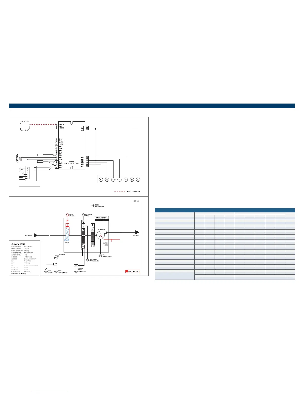
11.14 HP + HGRH + LP + (DFS-PSS)
UNIT TERMINAL BLOCK
TO BACnet
MS/TP
NETWORK
LWTS
STANDARD COMPONENTS:
DATS - DISCHARGE AIR TEMPERATURE SENSOR
LWTS - LEAVING WATER TEMPERATURE SENSOR
REFER TO UNIT WIRING DIAGRAM FOR FURTHER DETAILS
DATS
T1
T2
A
A
B
B
C
C
641-264
IEM
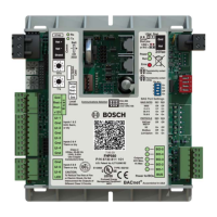
FHP560
Heat Pump Sequence of Operation – HP + HGRH + LP + (DFS-PSS)
Supply Fan Start/Stop:
The supply fan will be started according to the schedule. After the supply fan has been started the control sequence will be enabled.
Zone Control:
The compressor will cycle to maintain the zone temperature at setpoint.
Heat Pump Control:
When the zone temperature falls below the zone temperature setpoint the reversing valve will be disabled to provide heating when the
compressor is running. When the zone temperature rises above the zone temperature setpoint the reversing valve will be enabled to provide
cooling when the compressor is running.
Night Setback:
When in “unoccupied”, the unit will cycle as necessary to maintain the night setback zone temperature at setpoint.
Shutdown:
When the unit is shutdown by either a stop command or system safety the unit will be set as follows:
Supply fan will be on (user configurable)
Compressor(s) will be off
Dirty Filter Switch:
A fi eld installed status switch is used to provide a contact closure at the confi gured input (IN-5 or IEM) when the fi lter is ready to be serviced.
An alarm is generated immediately after the switch closes, and is available on a ZS Pro sensor, BACview interface, or over a network.
Hot Gas Reheat:
Once the heat/cool setpoint has been satisfi ed and relative humidity is above setpoint, the unit will operate in hot-gas reheat mode to actively
remove humidity from the space until the the humidity setpoint has been satisfi ed, or there’s another call for heating or cooling.
Relative humidity readings may be acquired from a space ZS combo Pro or base sensor, 0-5V sensor in IN-1/IN-2, or over a network; software must
be confi gured accordingly.
Circulating Water Pump (Loop Pump):
Factory installed loop pump with with optional current sensor for pump status verifi cation must be confi gured by the equipment integrator.
Upon a call for compressor operation the pump is indexed to run via BO-5 after 20 secs. Compressor operation is not enabled until sensor switch
is closed (pump is energized and running).
Pump status is verifi ed via the Pump Status Switch (current sensor) within 15 secs of pump enable command.
If Pump Status Switch (PSS) does not close within the 15 secs, pss fail alarm is initiated. If pump runs without command from BO-5, pump in hand
alarm is initiated.
Compressor operation is disabled 20 secs after PSS opens (fails) when pump has been indexed to run.
HEAT PUMP
Point Name
Hardware Points Software Points
Show On
Graphic
AI AO BI BO AV BV Sched Trend Alarm
Zone Temperature XXXX
Heating Setpoint XXX
Cooling Setpoint XXX
Supply Fan Command XXX
Compressor Stage 1 Output XXX
Compressor Stage 2 Output XX
Reversing Valve Command XXX
Occupied Command X XXX X
Discharge Air Temperature X X
Leaving Water Temperature X X
Loop Pump Command XX
Pump Status XX
Dehumidifi cation Setpoint XXX
Reheat Status
Reheat On/Off (Rh S/S) XXX
High Return Air Humidity X
Zone Humidity XXXX
Filter Status X XX
Filter Change Required X
Condensate Overfl ow XX
Lockout Alarm XX
Schedule
Totals
403553111516
Total Hardware Total Software
12 25 16
Table 22