16
|
FHP560 Controller Applications Manual
Bosch Thermotechnology Corp.
Data subject to change Page____ of ____
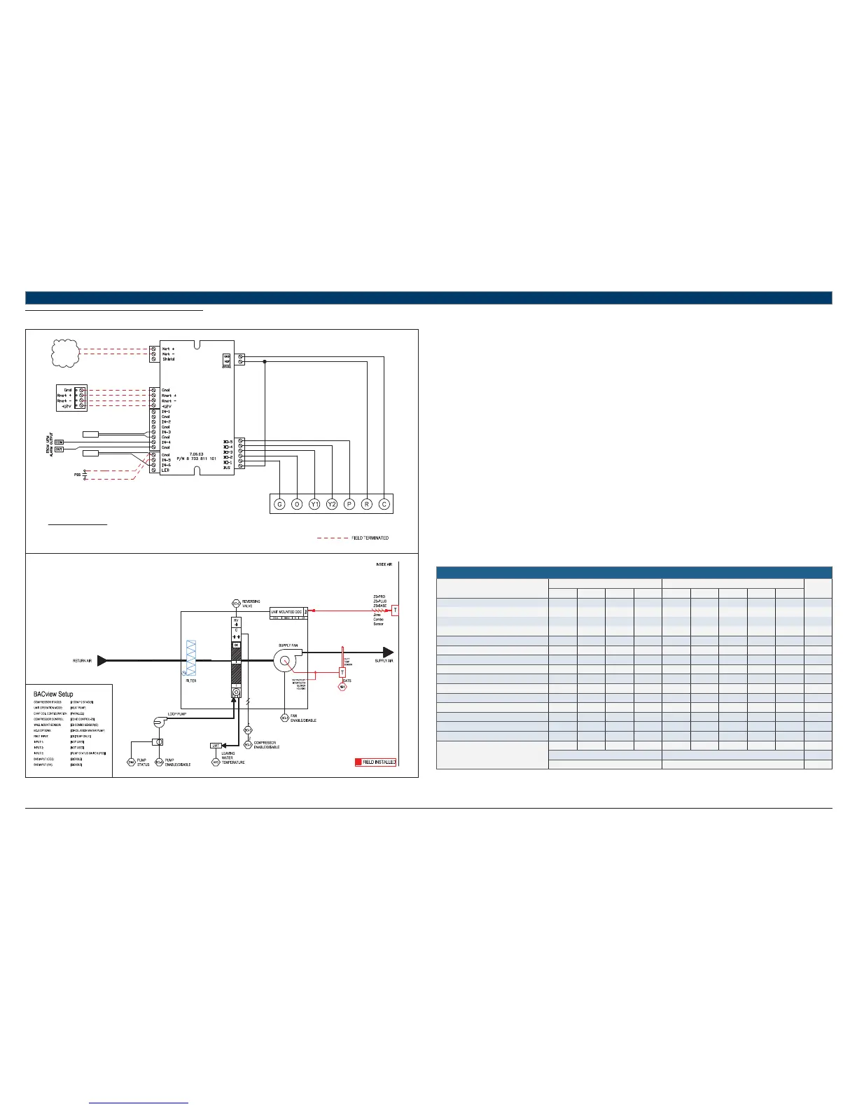
11.5 HP + LP
UNIT TERMINAL BLOCK
TO BACnet
MS/TP
NETWORK
LWTS
DATS
RED
GREEN
WHITE
BLACK
TERMINATION DETAIL
RNET: SENSORS
STANDARD COMPONENTS:
DATS - DISCHARGE AIR TEMPERATURE SENSOR
LWTS - LEAVING WATER TEMPERATURE SENSOR
REFER TO UNIT WIRING DIAGRAM FOR FURTHER DETAILS
FHP560
Heat Pump Sequence of Operation – HP + LP
Supply Fan Start/Stop:
The supply fan will be started according to the schedule. After the supply fan has been started the control sequence will be enabled.
Zone Control:
The compressor will cycle to maintain the zone temperature at setpoint.
Heat Pump Control:
When the zone temperature falls below the zone temperature setpoint the reversing valve will be disabled to provide heating when the
compressor is running. When the zone temperature rises above the zone temperature setpoint the reversing valve will be enabled to provide
cooling when the compressor is running.
Night Setback:
When in “unoccupied”, the unit will cycle as necessary to maintain the night setback zone temperature at setpoint.
Shutdown:
When the unit is shutdown by either a stop command or system safety the unit will be set as follows:
Supply fan will be on (user configurable)
Compressor(s) will be off
Circulating Water Pump (Loop Pump):
Factory installed loop pump with with optional current sensor for pump status verifi cation must be confi gured by the equipment integrator. Upon
a call for compressor operation the pump is indexed to run via a 24Vac signal at BO-5. If the Pump Status Switch (PSS) is confi gured, compressor
operation is not enabled until sensor switch is closed (pump is energized and running).
Pump status is verifi ed via the pump status switch (current sensor) within 15 secs of pump enable command.
If PSS does not close within the 15 secs, PSS fail alarm is initiated. If pump runs without command from BO-5, pump in hand alarm is initiated.
Compressor operation is disabled 20 secs after PSS opens (fails) when pump has been indexed to run.
HEAT PUMP
Point Name
Hardware Points Software Points
Show On
Graphic
AI AO BI BO AV BV Sched Trend Alarm
Zone Temperature X X X X
Heating Setpoint X
Cooling Setpoint X
Supply Fan Command X
Compressor Stage 1 Output X
Compressor Stage 2 Output X
Reversing Valve Command X
Occupied Command X X X X
Discharge Air Temperature X X
Leaving Water Temperature X X
Loop Pump Command X X
Pump Status Switch X X
Condensate Overfl ow X
Lockout Alarm X
Schedule
Totals
3025531122
Total Hardware Total Software
10 12 2
Table 13