Applications Manual FHP560 Controller | 43
Bosch Thermotechnology Corp.
Data subject to changePage____ of ____
14.12 Rnet Tags
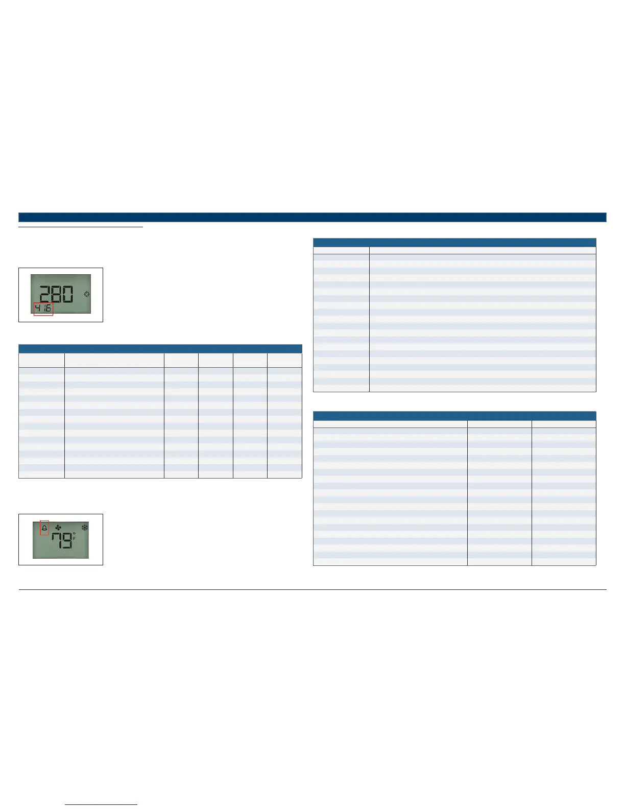
Rnet tags are numbers that identify types of system values, and determine how the ZS sensor will display those values. For example:
The Rnet tag number 100 indicates Fan Status. The sensor will display a fan icon when the microblock is active.
The Rnet tag number 416 indicates Air Flow Setpoint. Values such as this that do not have an icon will display the Rnet tag number in the
lower left corner of the sensor’s display.
Fig. 20
Below is a list of information provided by the ZS Pro Combo Sensor when the info button is pressed:
Information Displayed When Info Button is Pressed
Press info button this
number of times
Information Displayed Rnet Tag Number Read Only Inactive Text Active Text
1* Occupied Cooling Setpoint n/a
2 Occupied Heating Setpoint n/a
3 Unoccupied Cooling Setpoint n/a
4 Unoccupied Heating Setpoint n/a
5 Effective Cooling Setpoint n/a
6 Effective Heating Setpoint n/a
7 Occupied Zone Humidity Setpoint 406
8 Outdoor Air Temperature (OAT) 300
9 Aux Heat Output Command 1102
Off On
10 Effective Discharge Air Temperature (DAT) 304
11 Leaving Water Temperature (LWT) 319
12 Current Alarm Condition/Code 1300
13 Zone Mode Status 501
14 Compressor Stage 1 Status 1100
C1 Off C1 On
15 Compressor Stage 2 Status 1101
C2 Off C2 On
16 Economizer Mode Status 116
Econ Off Econ On
Table 46
* If there’s an active alarm(s) condition, pressing the info button once will fi rst display the alarm page including the corresponding Rnet tag and a short
text, before resuming the regular cycle of functions.
Alarm conditions are indicated by the bell symbol appearing on the Pro sensor display:
Fig. 21
The following is a description of the available alarm codes on the “Current Alarm Condition/Code” screen (Rnet tag 1300):
Available Alarm Codes
Alarm Code Description
0 System Normal - No Alarms
1 UPM code for High Pressure on circuit #1 fault
2 UPM code for Low Pressure on circuit #1 fault
3 UPM code for High Pressure on circuit #2 fault
4 UPM code for Low Pressure on circuit #2 fault
5 UPM code for Water Coil Freeze on circuit #1 fault
6 UPM code for High Condensate fault
7 UPM code for Brownout fault
8 UPM code for Air Coil Freeze on circuit #1 fault
9 UPM code for Water Coil Freeze on circuit #2 fault
10 UPM code for Air Coil Freeze on circuit #2 fault
20 FHP560 Input/Output in MANUAL lock position
30 Wired Sensor Failure for ZS Sensor, DAT Sensor, LWT Sensor, Humidity Sensor or CO₂ Sensor
40 High or Low Leaving Water Temperature (LWT) Condition
50 High or Low Zone Temperature Condition
60 High or Low Discharge Air Temperature (DAT) Condition
70 Filter or Compressor Runtime Alert
80 High or Low Zone Humidity Condition
90 High Zone CO₂ Condition
100 Differential Pressure Switch (DPS) Open Condition
Table 47
If an alarm is generated for any of the below conditions, pressing the info button will show a short “active text” and Rnet tag:
Alarm Active Text and Rnet Tag Number:
Alarm Display Information Rnet Tag Number Active Text
Filter Change Status 1027 FILTER
Low Zone Temp Alarm 1026 Lo ZTp
High Zone CO₂ Alarm 1043 Hi CO₂
High Zone Humidity Alarm 1044 Hi RH
Low Zone Humidity Alarm 1045 Lo RH
Compressor1 Runtime Alarm 1050 C1 RT
Compressor2 Runtime Alarm 1051 C2 RT
High Discharge Air Temp Alarm 1028 Hi DAT
Low Discharge Air Temp Alarm 1029 Lo DAT
Manual I/O Lock Alarm 1116 IO OVRD
Wired Sensor Faliure Alarm 1115 SEN Conn
High Leaving Water Temp Alarm 1113 Load H2O
Low Leaving Water Temp Alarm 1114 Load H2O
High Zone Temp Alarm 1025 Hi ZTp
DPS Lock Alarm 1117 DPS
UPM General High Pressure Alarm 1118 HP Fault
UPM General Low Pressure Alarm 1119 LP Fault
UPM General Freezestat Alarm 1120 Frz stat
UPM Brownout BRN Alarm 1109 Brn Out
UPM Condensate COND Alarm 1108 Hi Cond
Table 48