Applications Manual FHP560 Controller | 23
Bosch Thermotechnology Corp.
Data subject to changePage____ of ____
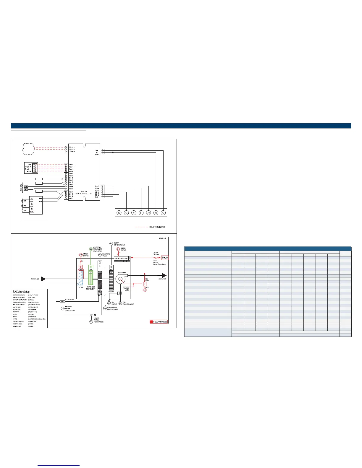
11.12 HP + ECONOMIZER + HGRH + (SDS-FSS-DFS)
UNIT TERMINAL BLOCK
TO BACnet
MS/TP
NETWORK
LWTS
RED
GREEN
WHITE
BLACK
TERMINATION DETAIL
RNET: SENSORS
ZS COMBO SENSOR (TEMP+RH)
STANDARD COMPONENTS:
DATS - DISCHARGE AIR TEMPERATURE SENSOR
LWTS - LEAVING WATER TEMPERATURE SENSOR
EWTS - ENTERING WATER TEMPERATURE SENSOR
REFER TO UNIT WIRING DIAGRAM FOR FURTHER DETAILS
EWTS
DATS
T1
T2
A
A
B
B
C
C
641-264
IEM
FHP560
Heat Pump Sequence of Operation – HP + ECONOMIZER + HGRH + (SDS-FSS-DFS)
Supply Fan Start/Stop:
The supply fan will be started according to the schedule. After the supply fan has been started the control sequence will be enabled.
Zone Control:
The compressor will cycle to maintain the zone temperature at setpoint.
Heat Pump Control:
When the zone temperature falls below the zone temperature setpoint the reversing valve will be disabled to provide heating when the
compressor is running. When the zone temperature rises above the zone temperature setpoint the reversing valve will be enabled to provide
cooling when the compressor is running.
Night Setback:
When in “unoccupied”, the unit will cycle as necessary to maintain the night setback zone temperature at setpoint.
Smoke Detector Switch:
A fi eld installed smoke detector provides a contact closure at the confi gured input (IN-5 or IEM) during a smoke event, and will initiate emergency
shutdown procedures after 5 seconds.
When the unit is shutdown by the smoke detector the unit will be set as follows:
Supply fan will be off (user configurable)
Compressor(s) will be off
The unit may be confi gured to operate the fan during a smoke event for specifi c safety applications; system integrator must determine the
appropriate fan behavior.
Fan Status Switch:
The status output from a factory-installed current sensor provides a contact closure at the confi gured input (IN-5 or IEM) to prove fan operation.
The fan command output is disabled if a contact closure is not detected 35 secs after the unit fan is indexed on by the controller.
Dirty Filter Switch:
A fi eld installed status switch is used to provide a contact closure at the confi gured input (IN-5 or IEM) when the fi lter is ready to be serviced.
An alarm is generated immediately after the switch closes, and is available on a ZS Pro sensor, BACview interface, or over a network.
Economizer:
A factory installed Entering Water Temperature (EWT) sensor in IN-2 (the default IN-5 is occupied by the IEM ) is used to enable the economizer
mode during cooling operations. Entering water temperature values below 55°F (user confi gurable) will enable economizer mode.
Hot Gas Reheat:
Once the heat/cool setpoint has been satisfi ed and relative humidity is above setpoint, the unit will operate in hot-gas reheat mode to actively
remove humidity from the space until the the humidity setpoint has been satisfi ed, or there’s another call for heating or cooling.
HEAT PUMP
Point Name
Hardware Points Software Points
Show On
Graphic
AI AO BI BO AV BV Sched Trend Alarm
Zone Temperature XXXX
Heating Setpoint XXX
Cooling Setpoint XXX
Supply Fan Command XXX
Compressor Stage 1 Output XXX
Compressor Stage 2 Output XX
Reversing Valve Command XXX
Occupied Command X XXX X
Discharge Air Temperature X X
Leaving Water Temperature X X
Entering Water Temperature X
Economizer Valve Output X
Dehumidifi cation Setpoint XXX
Reheat Status
Reheat On/Off (Rh S/S) XXX
High Return Air Humidity X
Zone Humidity XXXX
Filter Status X XX
Filter Change Required X
Fan Status X X
Smoke Detector Status X X
Condensate Overfl ow XX
Lockout Alarm XX
Schedule
Totals
504551111716
Total Hardware Total Software
14 25 16
Table 20