Applications Manual FHP560 Controller | 19
Bosch Thermotechnology Corp.
Data subject to changePage____ of ____
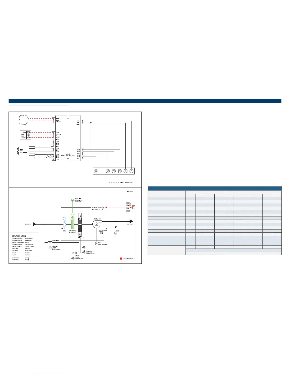
11.8 STRAIGHT COOL + ECONOMIZER
UNIT TERMINAL BLOCK
TO BACnet
MS/TP
NETWORK
LWTS
STANDARD COMPONENTS:
DATS - DISCHARGE AIR TEMPERATURE SENSOR
LWTS - LEAVING WATER TEMPERATURE SENSOR
EWTS - ENTERING WATER TEMPERATURE SENSOR
REFER TO UNIT WIRING DIAGRAM FOR FURTHER DETAILS
EWTS
DATS
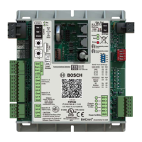
FHP560
RED
GREEN
WHITE
BLACK
TERMINATION DETAIL
RNET: SENSORS
Heat Pump Sequence of Operation – STRAIGHT COOL + ECONOMIZER
Supply Fan Start/Stop:
The supply fan will be started according to the schedule. After the supply fan has been started the control sequence will be enabled.
Zone Control:
The compressor will cycle to maintain the zone temperature at setpoint.
Straight Cool Control:
Unit is confi gured for mechanical cooling only and the reversing valve is not installed. BO-2 is disabled and unused.
Night Setback:
When in “unoccupied”, the unit will cycle as necessary to maintain the night setback zone temperature at setpoint.
Shutdown:
When the unit is shutdown by either a stop command or system safety the unit will be set as follows:
Supply fan will be on (user configurable)
Compressor(s) will be off
Economizer:
Water Side Economizer (WSE) option must be confi gured by the equipment integrator. A factory installed Entering Water Temperature (EWT)
sensor in IN-5 (IN-2 if IEM is present) is used to enable the economizer mode during cooling operations.
Entering water temperature values below 55°F (user confi gurable) will enable economizer mode.
A 3-way economizer valve is required for the WSE option and is connected to BO-5.
HEAT PUMP
Point Name
Hardware Points Software Points
Show On
Graphic
AI AO BI BO AV BV Sched Trend Alarm
Zone Temperature X X X X
Heating Setpoint X
Cooling Setpoint X
Supply Fan Command X
Compressor Stage 1 Output X
Compressor Stage 2 Output X
Reversing Valve Command
Occupied Command X X X X
Discharge Air Temperature X
Leaving Water Temperature X
Entering Water Temperature X
Economizer Valve Output X
Condensate Overfl ow X
Lockout Alarm X
Schedule
Totals
4014311122
Total Hardware Total Software
982
Table 16