Applications Manual FHP560 Controller | 17
Bosch Thermotechnology Corp.
Data subject to changePage____ of ____
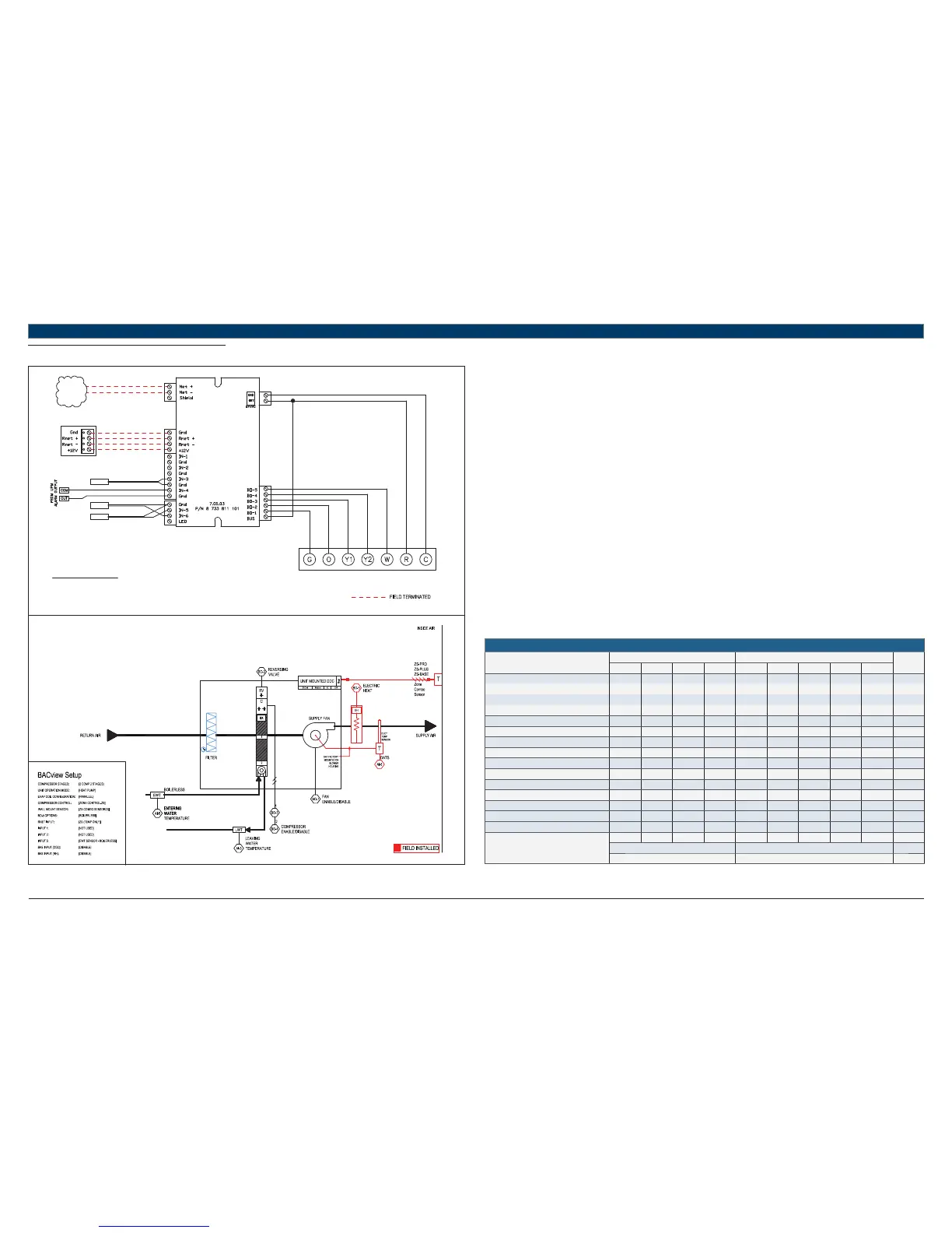
11.6 HP + BOILERLESS
UNIT TERMINAL BLOCK
TO BACnet
MS/TP
NETWORK
LWTS
DATS
RED
GREEN
WHITE
BLACK
TERMINATION DETAIL
RNET: SENSORS
STANDARD COMPONENTS:
DATS - DISCHARGE AIR TEMPERATURE SENSOR
LWTS - LEAVING WATER TEMPERATURE SENSOR
EWTS - ENTERING WATER TEMPERATURE SENSOR
REFER TO UNIT WIRING DIAGRAM FOR FURTHER DETAILS
EWTS
FHP560
Heat Pump Sequence of Operation – HP + BOILERLESS
Supply Fan Start/Stop:
The supply fan will be started according to the schedule. After the supply fan has been started the control sequence will be enabled.
Zone Control:
The compressor will cycle to maintain the zone temperature at setpoint.
Heat Pump Control:
When the zone temperature falls below the zone temperature setpoint the reversing valve will be disabled to provide heating when the
compressor is running. When the zone temperature rises above the zone temperature setpoint the reversing valve will be enabled to provide
cooling when the compressor is running.
Night Setback:
When in “unoccupied”, the unit will cycle as necessary to maintain the night setback zone temperature at setpoint.
Shutdown:
When the unit is shutdown by either a stop command or system safety the unit will be set as follows:
Supply fan will be on (user configurable)
Compressor(s) will be off
Boilerless Control:
Boilerless control (BLC) option must be confi gured by the equipment integrator. A factory installed entering water temperature sensor in IN-5
(IN-2 if IN-5 is unavailable) is used to enable boilerless control.
Entering water temperature values less than 40°F (user confi gurable) will enable boilerless control.
Compressor operation is disabled upon boilerless control signal being activated.
An electric heat package must be installed for boilerless control option. Electric heat will be enabled on binary output BO-5 when boilerless signal
is activated.
HEAT PUMP
Point Name
Hardware Points Software Points
Show On
Graphic
AI AO BI BO AV BV Sched Trend Alarm
Zone Temperature X X X X
Heating Setpoint X
Cooling Setpoint X
Supply Fan Command X
Compressor Stage 1 Output X
Compressor Stage 2 Output X
Reversing Valve Command X
Occupied Command X X X X
Discharge Air Temperature X
Leaving Water Temperature X
Entering Water Temperature X
Aux Electric Heat Output X
Condensate Overfl ow X
Lockout Alarm X
Schedule
Totals
4015311122
Total Hardware Total Software
10 8 2
Table 14