14
|
FHP560 Controller Applications Manual
Bosch Thermotechnology Corp.
Data subject to change Page____ of ____
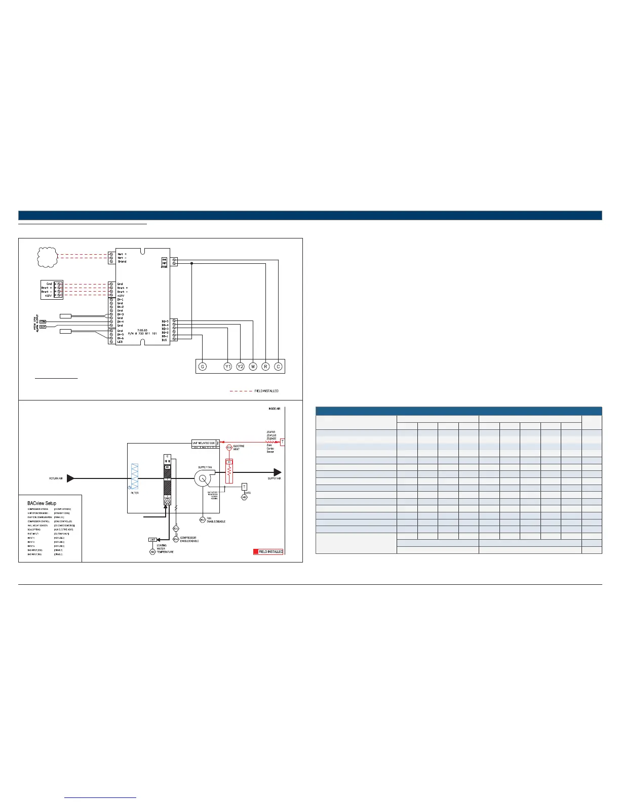
11.3 STRAIGHT COOL + EH
UNIT TERMINAL BLOCK
TO BACnet
MS/TP
NETWORK
LWTS
RED
GREEN
WHITE
BLACK
TERMINATION DETAIL
RNET: SENSORS
STANDARD COMPONENTS:
DATS - DISCHARGE AIR TEMPERATURE SENSOR
LWTS - LEAVING WATER TEMPERATURE SENSOR
REFER TO UNIT WIRING DIAGRAM FOR FURTHER DETAILS
FHP560
DATS
Heat Pump Sequence of Operation – STRAIGHT COOL + EH
Supply Fan Start/Stop:
The supply fan will be started according to the schedule. After the supply fan has been started the control sequence will be enabled.
Zone Control:
The compressor will cycle to maintain the zone temperature at setpoint.
Straight Cool Control:
Unit is confi gured for mechanical cooling only and the reversing valve is not installed. BO-2 is disabled and unused.
Night Setback:
When in “unoccupied”, the unit will cycle as necessary to maintain the night setback zone temperature at setpoint. A differential prevents the unit
from cycling excessively.
Shutdown:
When the unit is shutdown by either a stop command or system safety the unit will be set as follows:
Supply fan will be on (user configurable)
Compressor(s) will be off
Auxiliary electric heat:
Electric Heat (EH) option may be factory or fi eld installed and must be confi gured by the equipment integrator. Only one (1) stage of auxiliary
electric heat is supported and may be confi gured for BO-4 (single stage compressor units) or BO-5 (dual stage compressor units).
Upon a call for heating with demand greater than 90% (user confi gurable), the EH signal will be enabled to maintain setpoint at the confi gured
output as follows:
Straight cool units: enabled with no delay
Single stage heat pump units: enabled 5 mins after first stage of mechanical heat if demand is still above 90%.
Dual stage heat pump units: enabled 5 mins after second stage of mechanical heat if demand is still above 90%.
HEAT PUMP
Point Name
Hardware Points Software Points
Show On
Graphic
AI AO BI BO AV BV Sched Trend Alarm
Zone Temperature X X X X
Heating Setpoint X
Cooling Setpoint X
Supply Fan Command X
Compressor Stage 1 Output X
Compressor Stage 2 Output X
Reversing Valve Command
Occupied Command X X X X
Discharge Air Temperature X
Leaving Water Temperature X
Entering Water Temperature X
Aux Electric Heat Output X
Condensate Overfl ow X
Lockout Alarm X
Schedule
Totals
4014311122
Total Hardware Total Software
982
Table 11