28
|
FHP560 Controller Applications Manual
Bosch Thermotechnology Corp.
Data subject to change Page____ of ____
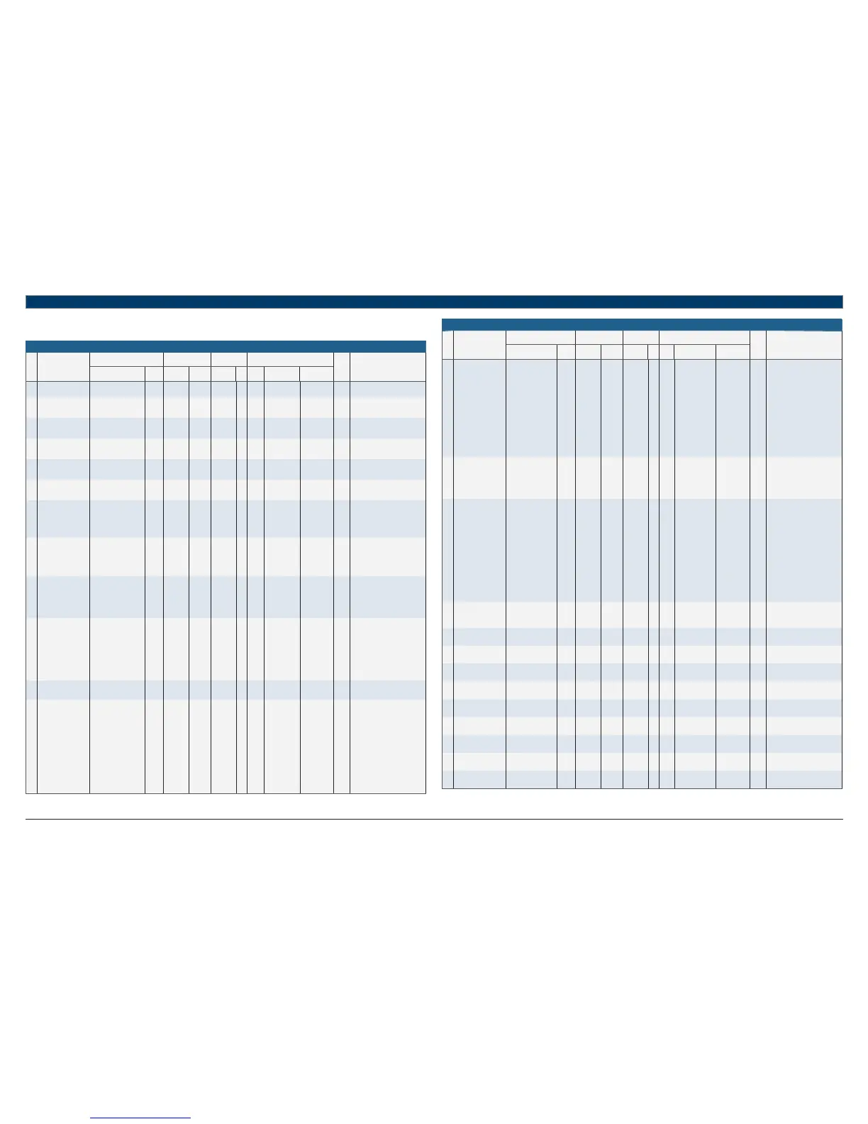
13 Integration Points List - Water-to-Air Standard Software 7.05.03
Integration Points
#
Point Description
Name
BACnet MODBUS N2 LON
Read
Only
Description
Name
Type
ID
Object
Type
Register Type ID
SNVT
#
Name SNVT
1 BAS CO₂ Sensor Value bas_CO₂_val_1 AV:49 fl oat value 40001 data fl oat 1 1 nviBasCO₂Val SNVT_ppm(29)
BAS CO₂ Sensor Value in PPM
Default: 1001 PPM
2 BAS Mixed Air Temp bas_mat_1 AV:86 fl oat value 40003 data fl oat 2 ‒‒ ‒
BAS Mixed Air Temperature Value
in °F
Default: 66.5 °F
3
BAS Outside Air
Temperature
effective_oat_1 AV:29 fl oat value 40005 data fl oat 3 0 nviEffectiveOAT
SNVT_
temp_p(105)
Effective Outside Air Temperature
in °F
Default: 60 °F
4 BAS RH Sensor Value bas_rh_sen_val_1 AV:56 fl oat value 40007 data fl oat 4 15 nviBasRhSenVal
SNVT_lev_
percent(81)
RH Sensor Value Supplied by BAS
in %
Default: 56 %RH
5
BAS Temperature
Sensor Value
bas_sen_val_1 AV:19 fl oat value 40009 data fl oat 5 2 nviBasSenVal
SNVT_
temp_p(105)
BAS Zone Temperature Sensor
Value in °F
Default: 74 °F
6
Evaporator Coil
Confi guration Selection
coil_cfg_1 AV:94 fl oat value 40011 data fl oat 6 ‒‒ ‒
Coil Confi guration Setup
0 = Parallel (Default)
1 = Series
7
Compressor Control
Mode
comp_mode_1 AV:64 fl oat value 40013 data fl oat 8 ‒‒ ‒
Compressor Mode Setup
0 = Zone Control - ZS (Default)
1 = Discharge Air Control
2 = Zone Control - BAS Sensor
3 = Zone Control - Remote Sensor
8 Compressor Stages cmp_stgs_1 AV:14 fl oat value 40001 data fl oat 7 16 nvoCmpStgs
SNVT_count_
inc(9)
Reports Confi guration Status of
Compressor Stages
1 = 1 Compressor 1 Stage
2 = 2 Compressor 2 Stages
5 = 1 Compressor 2 Stages
9
Compressor Stages
Selection
stages_1 AV:114 fl oat value 40107 data fl
oat 79 ‒‒ ‒
Selected Compressor Stages
(Confi gured at Factory)
1 = 1 Compressor 1 Stage
2 = 2 Compressor 2 Stages
5 = 1 Compressor 2 Stages
(Default)
10 Control Source ctrl_source_1 AV:15 fl oat value 40023 data fl oat 12 3 nviCtrlSource
SNVT_count_
inc(9)
Control Source for Occupancy
Setup
0 = Digital Input Enable (e.g. Room
Occupancy Sensor)
1 = Keypad Schedule
2 = BAS Occupancy Command
(Default)
3 = Factory Use Only
4 = Manual On-Continuous
11
Cooling Demand
Percentage
clg_pct_1 AV:13 fl oat value 40025 data fl oat 13 ‒‒ ‒
Cooling Status in Demand Percent,
%
12 IN-2 Mode Status ui2_mode_status_1 AV:18 fl oat value 40033 data fl oat 55 ‒‒ ‒
Reports how the controller Input
#2 (IN-2) is confi gured
0 = Not Used
1 = Zone Remote Sensor
2 = Outdoor Air Temperature
Sensor
3 = Entering Water Temperature
Sensor
4 = Mixed Air Temperature Sensor
5 = Relative Humidity Sensor
(Probe)
6 = Digital Enable (e.g. Room
Occupancy Sensor)
7 = Return Air Temperature Sensor
Table 23
Integration Points
#
Point Description
Name
BACnet MODBUS N2 LON
Read
Only
Description
Name
Type
ID
Object
Type
Register Type ID
SNVT
#
Name SNVT
13
Current Alarm
Condition Status
current_alarm_1 AV:17 fl oat value 40003 data fl oat 9 17 nvoCurrentAlarm
SNVT_count_
inc(9)
Alarm Status of unit:
0 = No Alarm,
1-10 = UPM Fault Code
20 = Output Overridden via Keypad
30 = Sensor Failure
40 = Leaving Water Temp Alarm
50 = Zone Temp Alarm
60 = Discharge Air Temperature
Alarm
70 = Filter Alarm/Compressors 1 &
2 Runtime
80 = Zone Humidity Alarm
90 = High CO₂ Level Alarm
100 = Differential Pressure Switch
(DPS) Alarm"
14
Damper Occupancy
Selection
mdpr_occ_sel_1 AV:97 fl oat value 40031 data fl oat 16 ‒‒ ‒
Damper Occupancy Selection
Setup
0 = Disabled
1 = Occupied (Default)
2 = Unoccupied
3 = Any Occupancy
15
DI5 Mode (Digital
Input 5)
di5_mode_1 AV:60 fl oat value 40015 data fl oat 10 ‒‒ ‒
Controller Input #5 Confi guration
Selection
0 = Dirty Filter Switch
1 = Entering Water Temp Sensor -
Economizer/Boilerless
2 = Differential Pressure Switch
3 = Secondary Condensate Pan
4 = Fan Status Switch
5 = Valve End Switch
6 = Damper End Switch
7 = Smoke Detector Switch
8 = Pump Status Switch
9 = MIxed Air Temp Sensor - Mixed
Air Control
10 = Input Expansion Module (IEM)
11 = Not Used (Default)
16
Discharged Air
Temperature Setpoint
dat_stpt_1 AV:30 fl oat value 40017 data fl oat 11 18 nviDatStpt
SNVT_
temp_p(105)
Discharged Air Temperature
Setpoint Setup in °F
Default: 65 °F
17
Effective Cooling
Setpoint
eff_clg_stpt_1 AV:5 fl oat value 40039 data fl oat 20 4 nvoEffClgStpt
SNVT_
temp_p(105)
Effective Cooling Setpoint (after
setpoint adjustment applied) in °F
18 Effect Disch Air Temp eff_dat_1 AV:10 fl oat value 40011 data fl oat 18 21 nvoEffDat
SNVT_
temp_p(105)
Discharge Air Temperature (DAT)
in °F
19
Entering Water
Temperature
eff_ewt_1 AV:62 fl oat value 40013 data fl oat 19 22 nvoEffEwt
SNVT_
temp_p(105)
Water Side Economizer Effective
Entering Water Temperature in °F
20
Effective Heating
Setpoint
eff_htg_stpt_1 AV:6
fl oat value 40045 data fl oat 23 5 nvoEffHtgStpt
SNVT_
temp_p(105)
Effective Heating Setpoint (after
setpoint adjustment applied) in °F
21
Modulating Damper
Position
eff_dpr_pos_screen_1 AV:81 fl oat value 40047 data fl oat 24 ‒‒ ‒
Effective Outside Air Damper
Position in %
22 Zone Humidity eff_zone_humid_1 AV:20 fl oat value 40021 data fl oat 26 24 nvoEffZoneHumid
SNVT_lev_
percent(81)
Effective Zone Humidity in Percent
RH (%)
23
Leaving Water
Temperature (LWT)
eff_lwt_1 AV:11 fl oat value 40015 data fl oat 21 23 nvoEffLwt
SNVT_
temp_p(105)
Effective Leaving Water
Temperature Status in °F
24
Mixed Air Temperature
(MAT)
eff_mat_1 AV:87 fl oat value 40017 data fl oat 22 ‒‒ ‒
Effective Mixed Air Temperature
in °F
25
Outdoor Air
Temperature (OAT)
eff_oat_1 AV:75 fl oat value 40055 data fl oat 28 6 nvoEffOat
SNVT_
temp_p(105)
Effective Outdoor Temperature
Status in °F
Table 24