24
|
FHP560 Controller Applications Manual
Bosch Thermotechnology Corp.
Data subject to change Page____ of ____
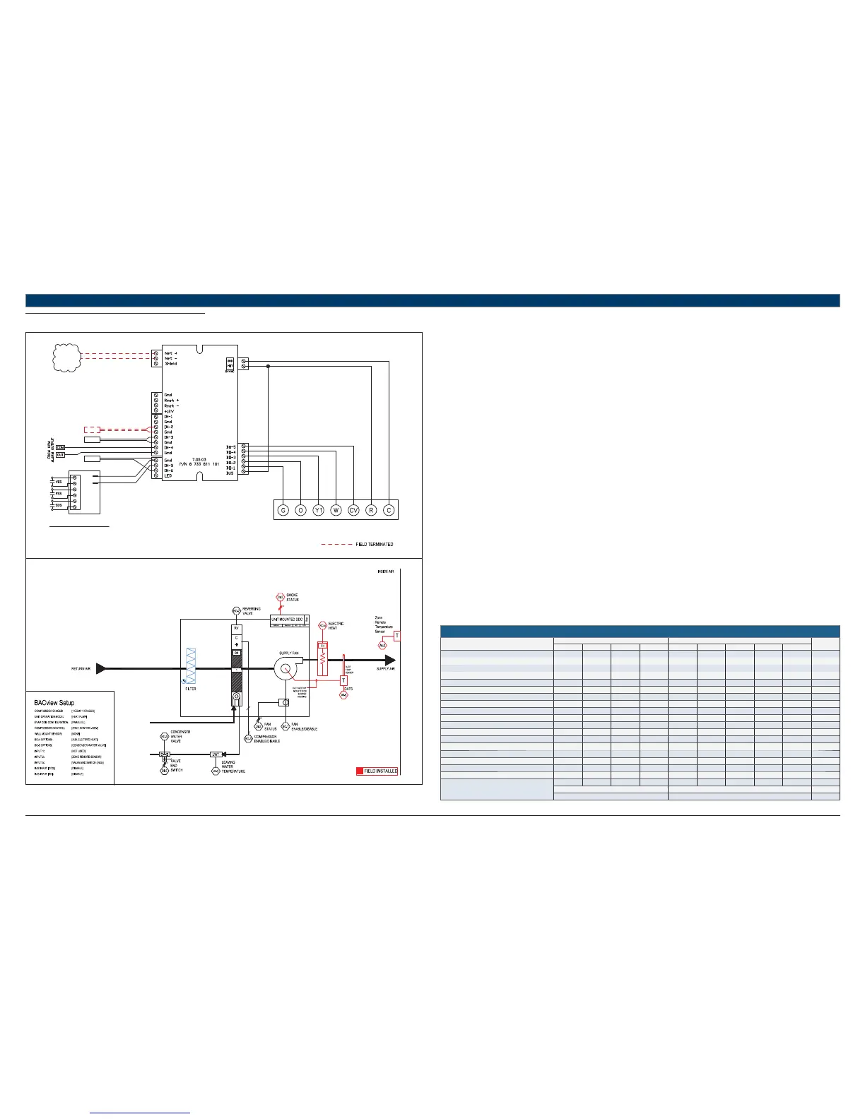
11.13 HP + EH + CWV + (SDS-FSS-VES)
UNIT TERMINAL BLOCK
TO BACnet
MS/TP
NETWORK
LWTS
STANDARD COMPONENTS:
DATS - DISCHARGE AIR TEMPERATURE SENSOR
LWTS - LEAVING WATER TEMPERATURE SENSOR
RTS - REMOTE TEMPERATURE SENSOR
REFER TO UNIT WIRING DIAGRAM FOR FURTHER DETAILS
DATS
FHP560
RTS
T1
T2
A
A
B
B
C
C
641-264
IEM
Heat Pump Sequence of Operation – HP + EH + CWV + (SDS-FSS-VES)
Supply Fan Start/Stop:
The supply fan will be started according to the schedule. After the supply fan has been started the control sequence will be enabled.
Zone Control:
The compressor will cycle to maintain the zone temperature at setpoint.
Heat Pump Control:
When the zone temperature falls below the zone temperature setpoint the reversing valve will be disabled to provide heating when the
compressor is running. When the zone temperature rises above the zone temperature setpoint the reversing valve will be enabled to provide
cooling when the compressor is running.
Night Setback:
When in “unoccupied”, the unit will cycle as necessary to maintain the night setback zone temperature at setpoint.
Smoke Detector Switch:
A fi eld installed smoke detector provides a contact closure at the confi gured input (IN-5 or IEM) during a smoke event, and will initiate emergency
shutdown procedures after 5 seconds.
When the unit is shutdown by the smoke detector the unit will be set as follows:
Supply fan will be off (user configurable)
Compressor(s) will be off
The unit may be confi gured to operate the fan during a smoke event for specifi c safety applications; system integrator must determine the
appropriate fan behavior.
Fan Status Switch:
The status output from a factory-installed current sensor provides a contact closure at the confi gured input (IN-5 or IEM) to prove fan operation.
The fan command output is disabled if a contact closure is not detected 35 secs after the unit fan is indexed on by the controller.
Auxiliary Electric Heat:
Electric Heat (EH) option may be factory or fi eld installed and must be confi gured by the equipment integrator. Only one (1) stage of auxiliary
electric heat is supported and may be confi gured for BO-4 (single stage compressor units) or BO-5 (dual stage compressor units).
Upon a call for heating with demand greater than 90% (user confi gurable), the EH signal will be enabled to maintain setpoint at the confi gured
output as follows:
Straight cool units: enabled with no delay
Single stage heat pump units: enabled 5 mins after first stage of mechanical heat if demand is still above 90%.
Dual stage heat pump units: enabled 5 mins after second stage of mechanical heat if demand is still above 90%.
Condenser Water Valve:
Factory installed loop valve with valve end switch (VES) option must be confi gured by the equipment integrator. Upon a call for compressor
operation the normally closed valve is indexed to open via BO-5 after 2.5 Mins. Compressor operation is not enabled until Valve End Switch is
engaged (valve fully open). Valve open status is verifi ed via the VES within 1.5 Mins of valve enable command.
If VES contacts do not engage within the specifi ed time, VES fail alarm is initiated. If valve opens without command from BO-5, valve in hand alarm
is initiated. Compressor operation is disabled 20 secs after VES opens (fails) when loop valve has been indexed to open.
HEAT PUMP
Point Name
Hardware Points Software Points
Show On
Graphic
AI AO BI BO AV BV Sched Trend Alarm
Zone Temperature XXXX
Heating Setpoint XXX
Cooling Setpoint XXX
Supply Fan Command XXX
Compressor Stage 1 Output XXX
Compressor Stage 2 Output XX
Reversing Valve Command XXX
Occupied Command X XXX X
Discharge Air Temperature X X
Leaving Water Temperature X X
Loop Valve Command XX
Valve End Switch (Valve Status) XX
Aux Electric Heat Output X
Fan Status X X
Smoke Detector Status X X
Condensate Overfl ow XX
Lockout Alarm XX
Schedule
Totals
30453318412
Total Hardware Total Software
12 19 12
Table 21