PRAESENSA Installation wiring | en 101
Bosch Security Systems B.V.
Underwriters Laboratories Listing Document (ULLD)
2021.12.21 | V0.15b | F.01U.402.882
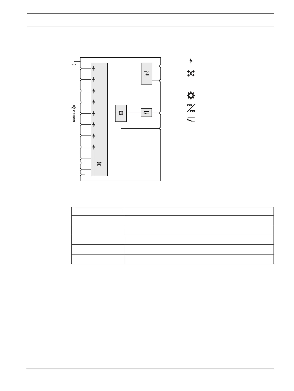
3.10.2 Functional diagram
Functional and connection diagram Internal device functions
PWR1
PWR2
P-Fail
Console
2
1
4
3
6
7
8
9
SFP
SFP
10
5
PoE
PoE
PoE
PoE
PoE
PoE
PoE
PoE
Power over Ethernet power source
OMNEO network switch
Socket for SFP module
Controller
DC to DC converter
Fault relay
3.10.3 Parts included
The box contains the following parts:
Quantity Component
1 10‑port industrial Ethernet switch
1 Screw connector
2 Wall-mounting bracket
1 DIN‑rail mounting bracket and screws
1 Startup manual
No tools or Ethernet cables are provided with the device.
3.10.4 Power supply connection
This Ethernet switch has a dual 48VDC-input and must be powered from the PRA-MPS3 to
one of the 48V outputs, normally intended for the amplifiers. Use both A and B outputs for
connection redundancy.
The 48V output that is powering the switch should not be used to also power an amplifier.
The lifeline that belongs to the powering 48V output is not used.
In case of mains failure the switch will be powered from the battery, connected to the
multifunction power supply.
3.10.5 Fault relay connection
The fault relay connection can not be used for UL864/UL2572 systems.