92 en | Installation wiring PRAESENSA
2021.12.21 | V0.15b | F.01U.402.882
Underwriters Laboratories Listing Document (ULLD)
Bosch Security Systems B.V.
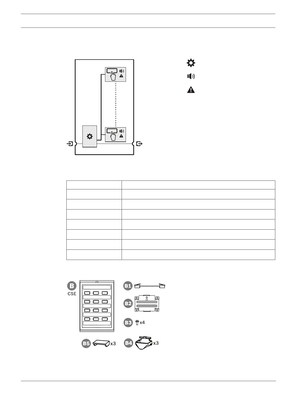
3.9.2 Functional diagram
Functional and connection diagram Internal device functions
Controller
Zone status indicator
Zone fault indicator
3.9.3 Parts included
The box contains the following parts:
Quantity Component
1 Call station extension
1 Bracket (attached to bottom)
1 Metal coupling plate + 4 screws
1 RJ12 interconnection cable
1 Button cap (x3)
1 Quick Installation Guide
1 Safety information
No tools or Ethernet cables are provided with the device.
Parts check and identification
B Call station extension
B1 Patch cable
B2 Coupling plate
B3 Screw torx TX10 (x4)
B4 Button light ring (x3)
B5 Button cap (x3)