PRAESENSA System Configuration | en 153
Bosch Security Systems B.V.
Underwriters Laboratories Listing Document (ULLD)
2021.12.21 | V0.15b | F.01U.402.882
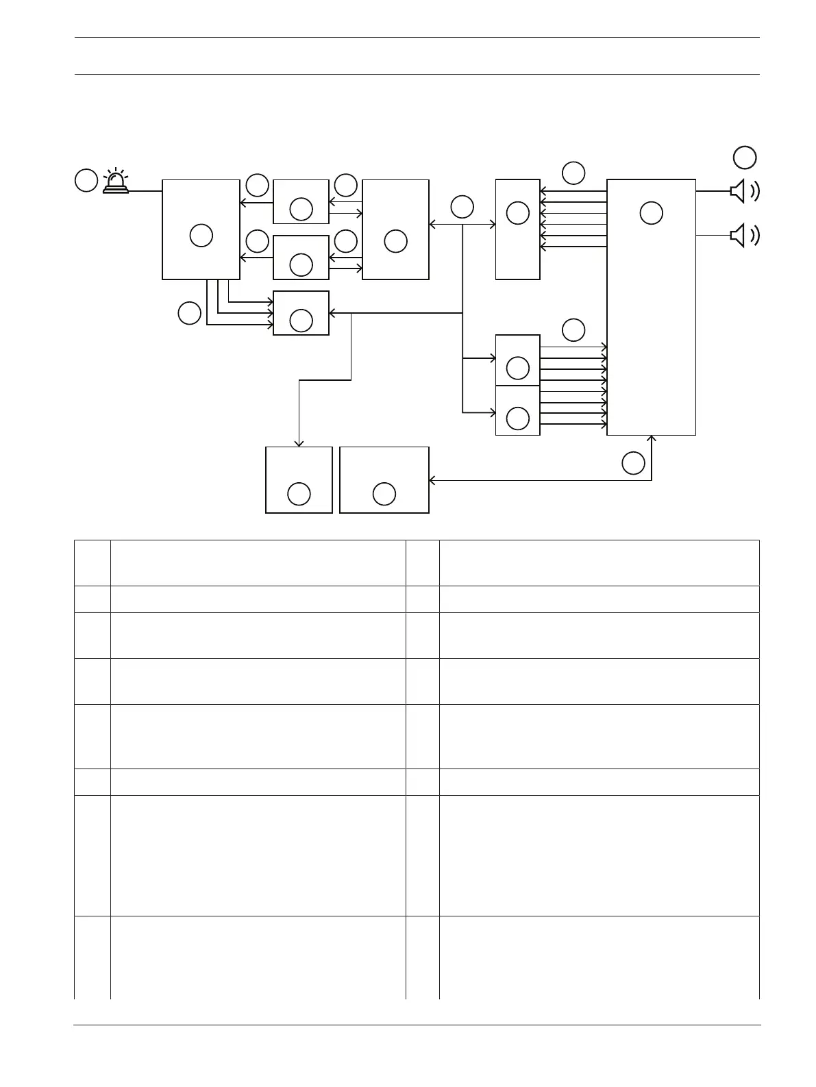
9.4 Interconnection with B9512G or B8512G panel
Scenario: B9512G or B8512G + PRA + 1 Strobe
9
G
10
B926M
PRA-FRP3-US
(LOC/ACU)
B308
B308
B208
B8512G
D192G
or
B9512G
11
I
7
7
H
86
5
3
F
DB
C
A
1
E
B208
4
2
D192GNAC
3
PRAESENSA
1 Clear strobe A Output signals from NAC (AC local, battery and
trouble)
2 NAC rack for strobes (R1002ULADA) B Notification output signal wiring for clear strobe
3 Notification appliance module (D192G) C Also for clear strobe, but can be used for second
strobe zone.
4 8‑input Expansion Module (B208) D Notification input- and output‑signal wiring for clear
strobe
5 Control panel (B9512G or B8512G) E Also for clear strobe, but can be used for second
strobe zone.
6 8‑input Expansion Module (B208) F SDI2 class b wiring
7 Octo‑output module (B308) G Connect the following output contact triggers from
the PRAESENSA output contacts to the B208 panel:
– Alarm Triggers and Trouble Signals from
PRAESENSA to B9512G or B8512G panel.
– Transfer of Control Signals
See
Control outputs, page 79
.
8 PRAESENSA system
See i.e.
PRAESENSA product overview, page 14
H Connect the following output contact triggers from
the B308 panel to the PRAESENSA input contacts:
– Alarm Triggers to start the MNS and Fire audio
messages in PRAESENSA.