110 en | Installation wiring PRAESENSA
2021.12.21 | V0.15b | F.01U.402.882
Underwriters Laboratories Listing Document (ULLD)
Bosch Security Systems B.V.
3.12.2 Functional diagram
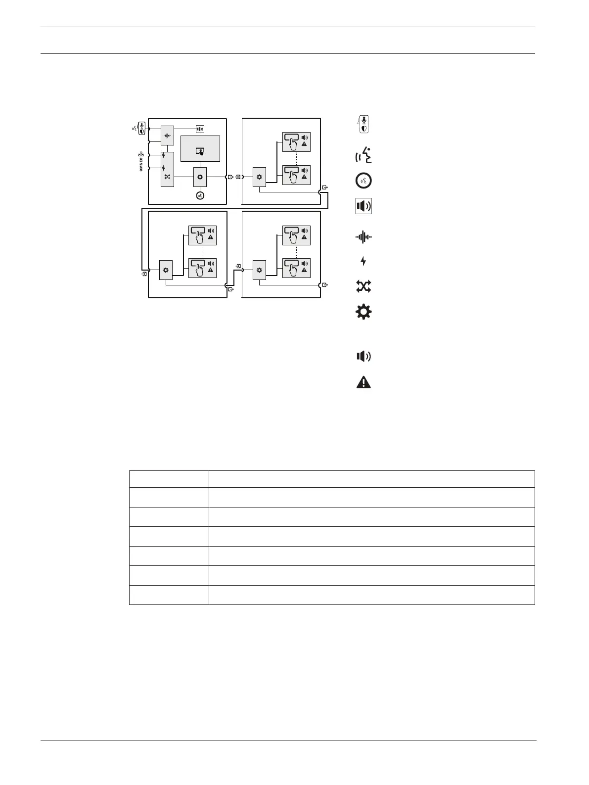
Functional and connection diagram Internal device functions
Fixed hand‑held microphone with
Press‑To‑Talk or Start/Stop switch
Press-To-Talk button
Call status LED ring
Internal monitor loudspeaker
(sounder)
Audio processing (DSP)
Power over Ethernet
OMNEO network switch
Controller
Zone status indicator
Zone trouble indicator
3.12.3 Parts included
The box contains the following parts:
Quantity Component
1 First responder panel
1 Key
4 Screws with screw covers
1 Trim rim
1 Operating instructions
1 Safety information
3.12.4 Installation instructions
The First responder panel is designed to be either surface or semi‑flush mounted. See
Surface
mount instructions, page 112
or
Semi-Flush mount instructions, page 115
. See figure below
for detailed dimensions.