30 en | Installation wiring PRAESENSA
2021.12.21 | V0.15b | F.01U.402.882
Underwriters Laboratories Listing Document (ULLD)
Bosch Security Systems B.V.
3.3.4 Power supply
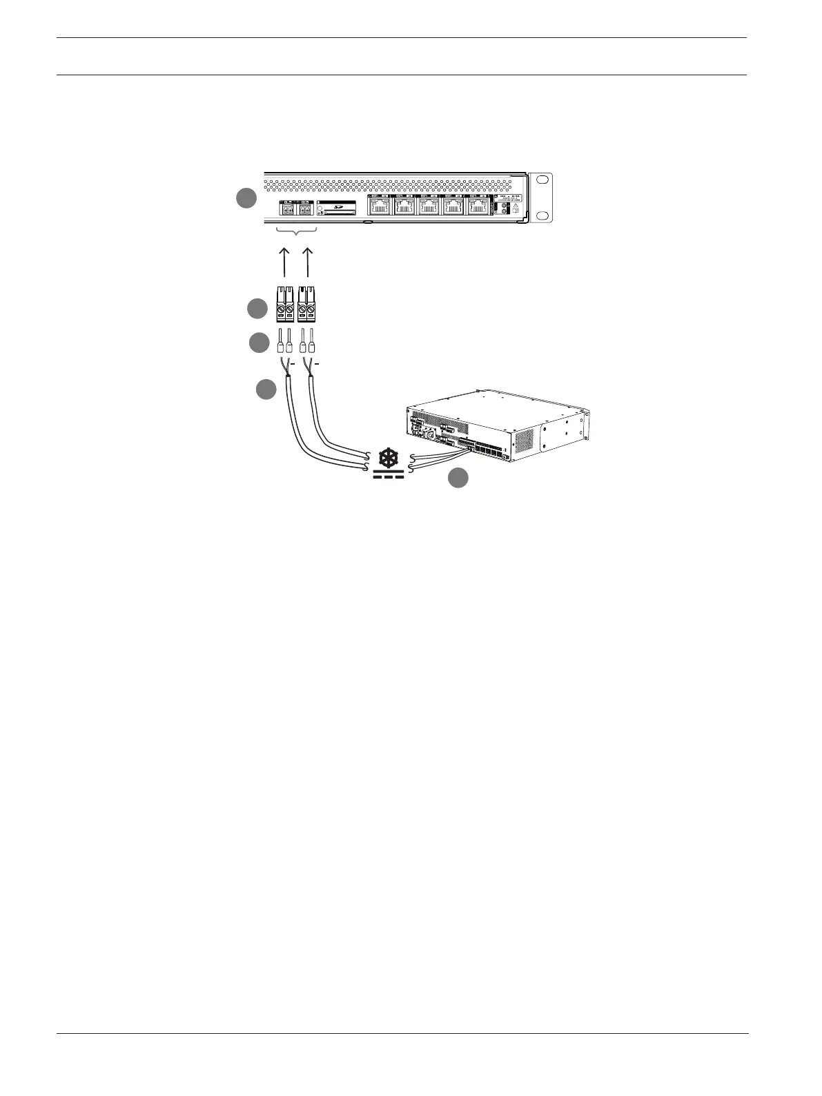
The system controller must be powered from the MPSx 24V output. It is recommended to use
double connections for fail-safe redundancy.
Follow the connection procedure below:
1. Crimp ferrules D onto the ends of the electrical wires of cable C to provide a solid and
reliable electrical connection. Use a dedicated crimping tool.
2. Insert each wire into the appropriate slot of the connector B, observing polarity. Wiring
color convention: red for + and black for -. Use a flat blade screwdriver to tighten each
connection.
3. Insert the cable into the 24 to 48V input A, cut the cable to length and mount the
connector of the powering device to the other end of the cable, again observing polarity.
Insert this connector into output A of the powering device (e.g. the 24V output of the
PRA-MPS3).
4. For redundancy, repeat these steps for a second cable to connect output B of the
powering device to input B of the system controller.