PRAESENSA System Configuration | en 157
Bosch Security Systems B.V.
Underwriters Laboratories Listing Document (ULLD)
2021.12.21 | V0.15b | F.01U.402.882
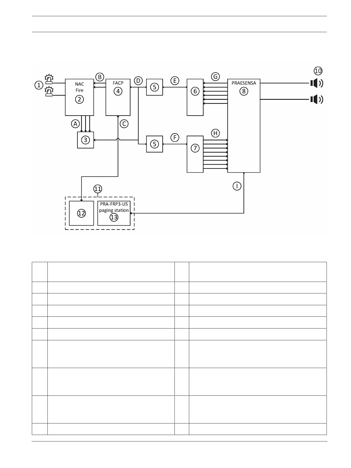
9.6 Generic interfacing with fire panel
Scenario: PRAESENSA with FACP (fire only) #
Remark: Multiple FRP panels are allowed, provided they are mounted adjacent to either the
fire panel or a fire annunciator that has control (Silence / Reset) buttons.
1 Clear fire strobes A Output signals from NAC (AC local, battery and
trouble)
2 NAC rack for fire strobes B Notification output wiring for fire strobe
3 FACP input contact module (addressable) C Interconnection wiring
4 FACP (Fire Alarm Control Panel) D Class b SLC wiring
5 Isolator (if required) E Class b SLC wiring
6 FACP input contact module (addressable) F Class b SLC wiring
7 FACP output contact module (addressable
relays)
G (Max. 8) Input contact wiring (e.g. Fire system, fire
trigger, trouble, battery, AC, etc.).
See
Control outputs, page 79
.
8 PRAESENSA system.
See i.e.
PRAESENSA product overview, page 14
.
H (Max. 8) Output contact wiring (e.g. Fire alarm, CO
alarm, etc.).
See
Control inputs, page 78
.
10 Loudspeaker / zones
See i.e.
Amplifier outputs, page 39
and
Amplifier
outputs, page 51
I Ethernet PoE (Class N) wiring
See
First responder panel | PRA-FRPx-US, PRA-FRPx-
USNY, page 108
.
11 Items 15 and 16 must be mounted side by side