52/60 Bosch Rexroth AG | Electric Drives and Controls LTH | 3 609 929 408/2.1
2 Power Unit LTH
2.10 Interface Description
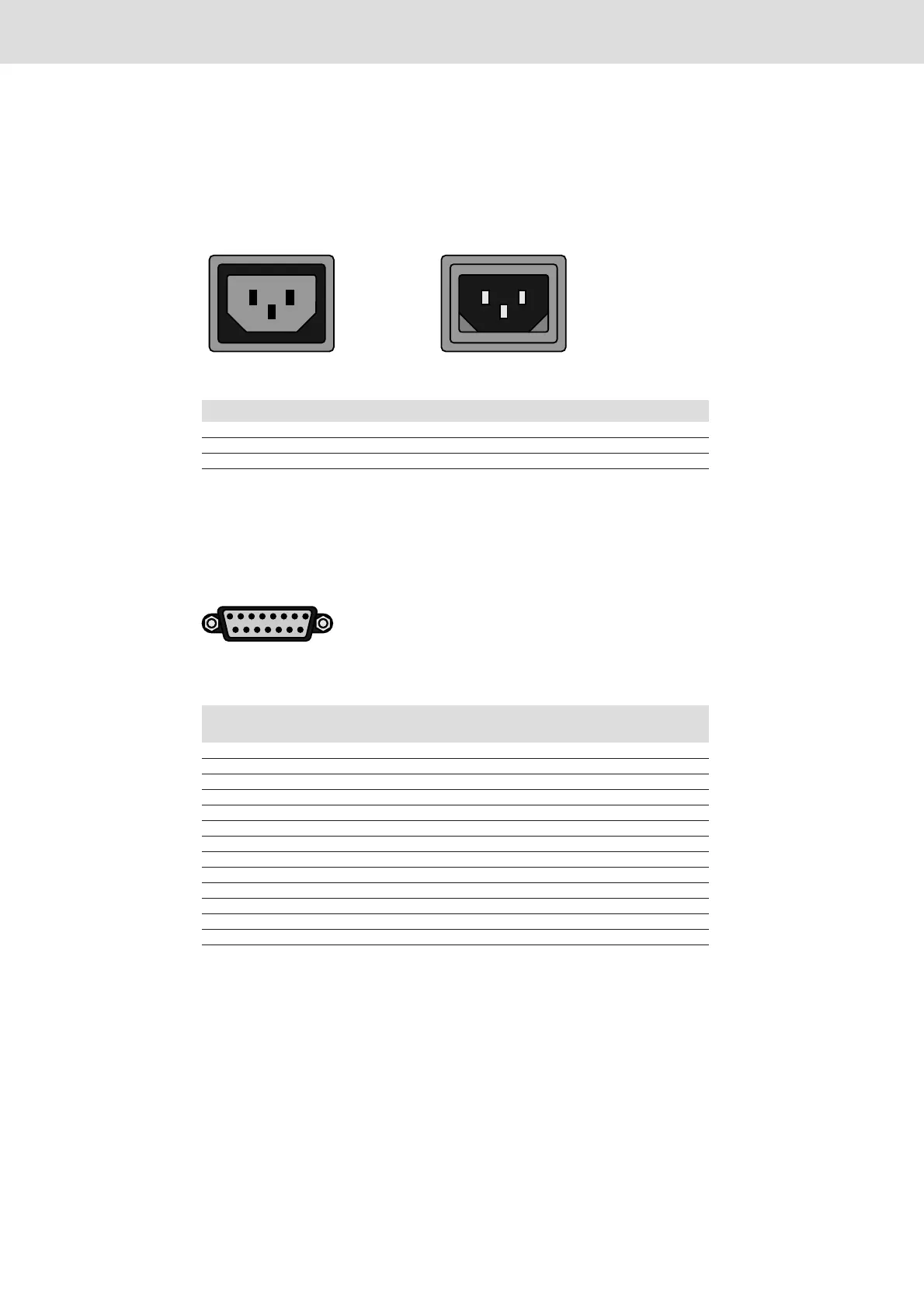
2.10.1 Power Line (X1)
IEC receptacle, male/female, 250V~/10A
Fig. 11:
2.10.2 Sensors SE200 (X2)
SUB-D connector, 15-pins, female
Fig. 12:
Pin-No. Signal Description/Function
L L Power line phase
N N Neutral conductor
PE PE Protective grounded conductor
Table 3:
Pin-No. Signal Input/Output
(I/O)
Description/Function
1 SHIELD Connected to housing
2 /CLK I Serial clock RS422 (inverted)
3 /DATA O Serial data RS422 (inverted)
4-5 - N.C.
6 0V Hand-held power tool reference potential
7 AUTO_0 I Data format switch-over
8 - N.C.
9 CLK I Serial clock RS422 (not inverted)
10 DATA O Serial data RS422 (not inverted)
11-12 - N.C.
13 0V Hand-held power tool reference potential
14 24VSE Supply from control
15 - N.C.
Table 4:
18
915
Artisan Technology Group - Quality Instrumentation ... Guaranteed | (888) 88-SOURCE | www.artisantg.com
 Loading...


