M1 – M3 Display Units
Page 80
Refer to chapter 7.3 (setup) to connect a MB-IO module
List of available functions :
Print, transfer the measured value
Set the display value to the master value
Set the display value to 0
Reset the dynamical measure
Start a dynamical measure
Output a signal if the characteristic is in the tolerance
Output a signal if the part is in the lower control limit
Output a signal if the part is in the upper control limit
Output a signal if the part is out lower tolerance
Output a signal if the part is out upper tolerance
Output a signal if the part is in the tolerances
Output a signal on a defined port for each class
Change the displayed characteristic
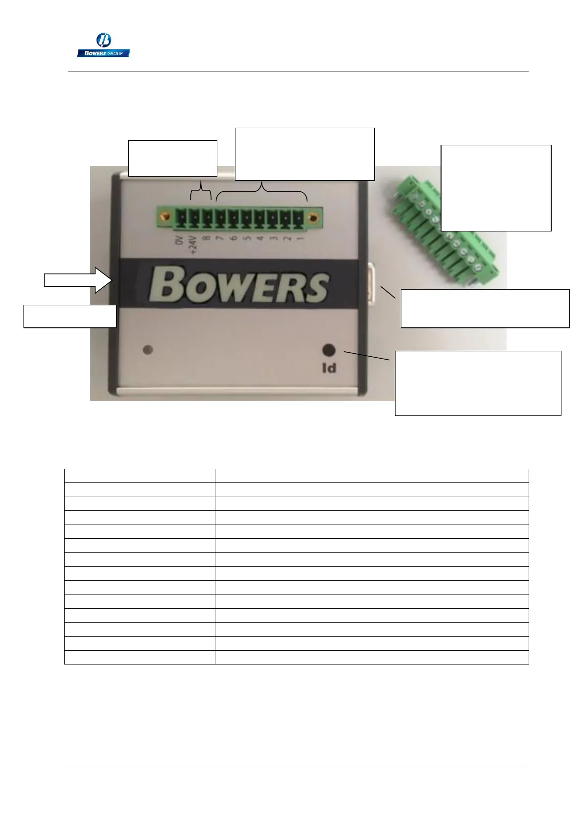
Terminal 1 to 8 : see
the below table
Male connector
with screw
terminals
(delivered with
the IO module)
Press on this button when
the M1/M3 is on the
« configuration » window .
Connect the next MB-IO
module here