118
11
Test Equipment
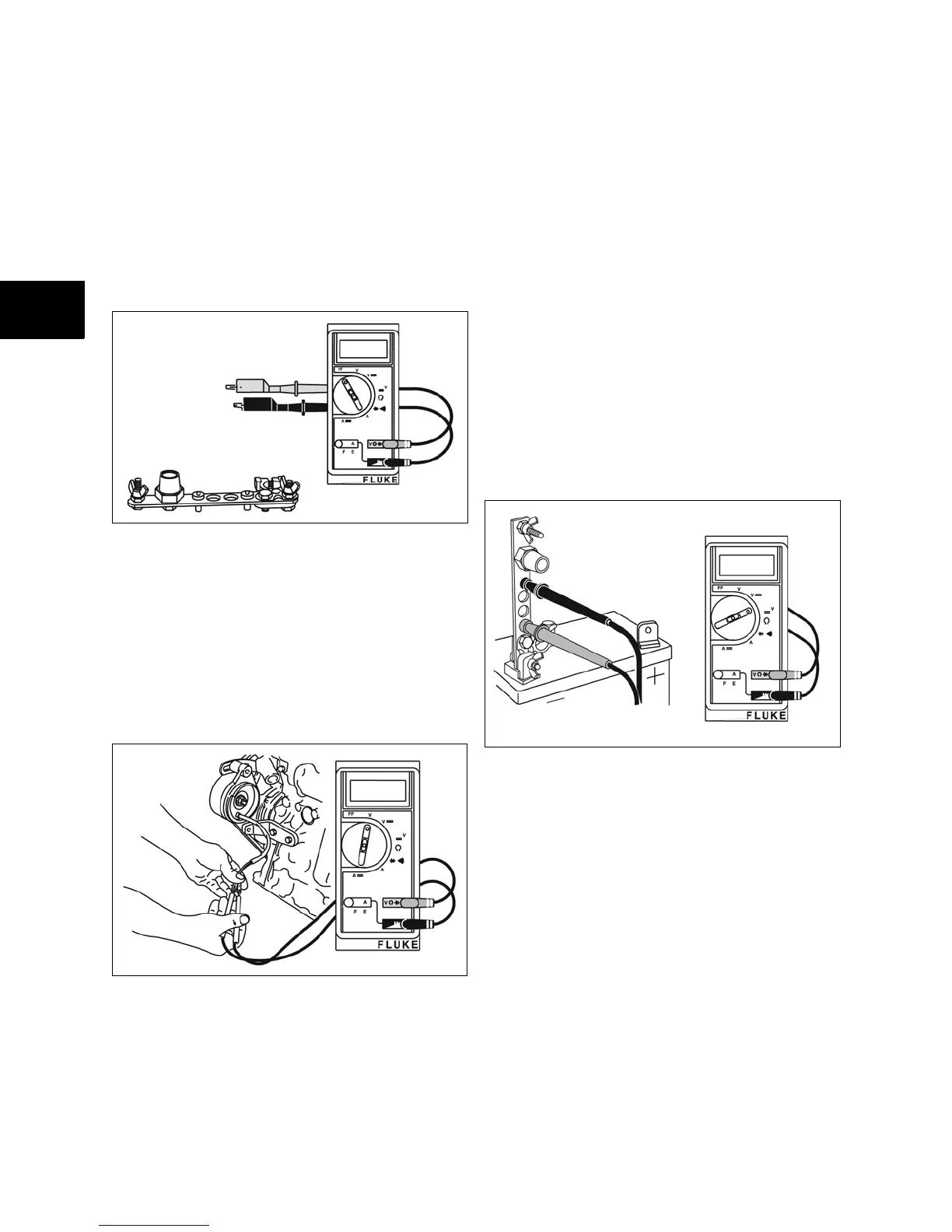
The Digital Multimeter #19390 and the DC Shunt,
#19468 (Figure 11), are required to test the
charging system.
NOTE: The digital multimeter will withstand DC
input of 10-20 amps for up to 30 seconds. To avoid
blowing the fuse in the meter, the DC shunt is
required.
Figure 11
Test Alternator - AC Output
1. The alternator output test will be performed
with the meter in the V~ (AC volts) position.
2. Disconnect the alternator wires at the
connector.
3. Attach meter test leads to alternator output
connectors BEFORE starting the engine
(Figure 12).
Figure 12
4. With the engine running at 3300 RPM the
output should be no less than 28 volts AC.
• If no output or low output is found, replace
the alternator.
• If alternator output is within specification,
reconnect alternator wires and test
regulator-rectifier.
Test Regulator-Rectifier - DC Output
NOTE: The DC shunt must be installed on the
negative (-) terminal of the battery (Figure 13). All
connections must be clean and tight for correct
amperage readings.
1. Attach meter test leads before starting
engine.
2. The regulator-rectifier test will be performed
in the 300mV== position.
3. Attach RED meter test lead to the RED post
terminal on shunt.
4. Attach BLACK meter test lead to BLACK post
terminal on shunt.
Figure 13
• With engine running at 3300 RPM, the
output should be 4-14 Amps.
• If no or low output is found, be sure that
the regulator-rectifier is grounded properly
and connections are clean and secure. If
there is still no or low output, replace the
regulator-rectifier.
 Loading...