70
10
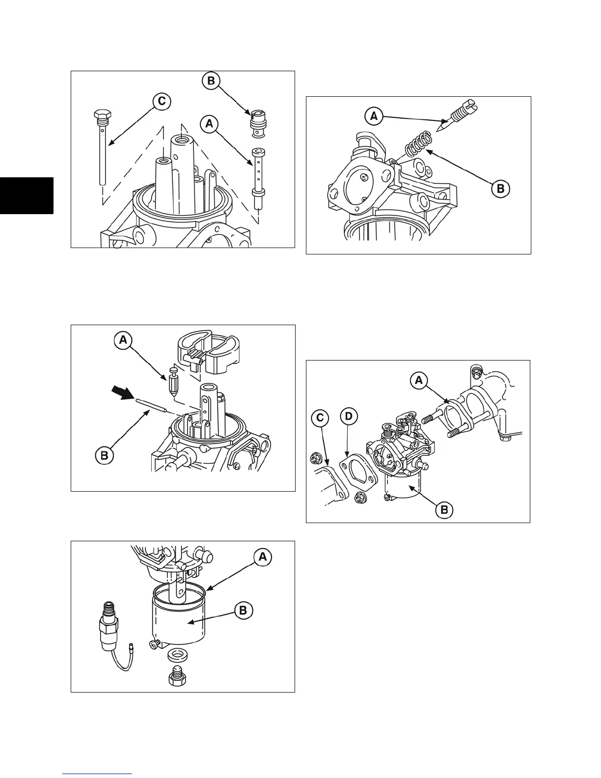
Figure 17
Install Float
1. Assemble inlet valve (A, Figure 18) to float.
2. Install float hinge pin (B) from throttle side of
carburetor.
Figure 18
3. Install gasket (A, Figure 19) and float bowl
(B).
Figure 19
4. Install idle mixture screw (A, Figure 20) and
spring (B).
Figure 20
NOTE: DO NOT tighten idle mixture screw.
Install Carburetor
1. Assemble insulator (A, Figure 21) with
gaskets, carburetor (B), and air horn (C) with
gasket (D) to intake manifold.
Figure 21
2. Torque nuts to values listed in Section 14 -
Engine Specifications.
3. Install governor link, spring, and choke link.
NOTE: Proceed to Step 5 if choke link is early style
with “Z” bend.
4. Reinstall air cleaner tube and fuel line.
5. Install choke link. Assemble governor control
bracket to intake manifold. Torque screws to
values listed in Section 14 - Engine
Specifications.
 Loading...