20
2
2
Figure 35
12. Install water pump with new gasket (Figure
36). Torque screws and nuts to values listed
in Section 14 - Engine Specifications.
Figure 36
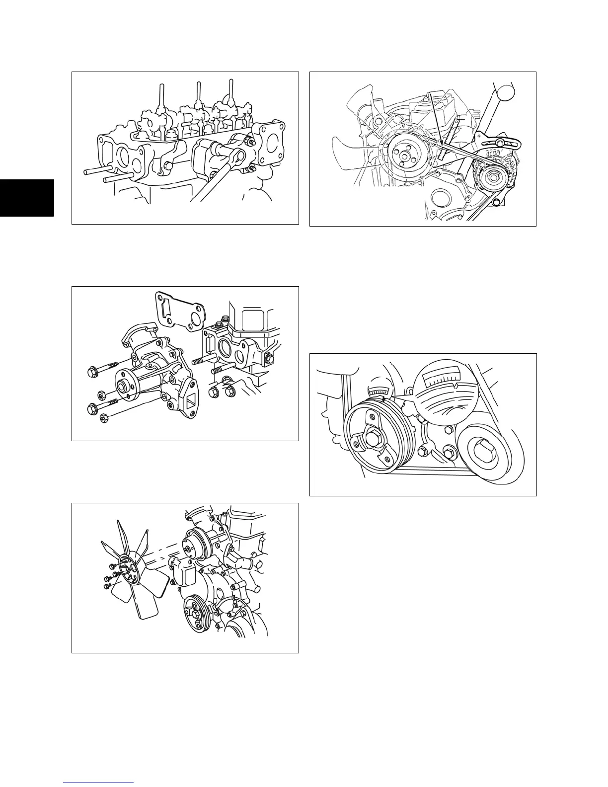
13. Install water pump pulley (Figure 37). Install
fan (if equipped). Torque screws to values
listed in Section 14 - Engine Specifications.
Figure 37
14. Install V-belt (Figure 38). Install alternator
adjusting bolt. Torque bolt to values listed in
Section 14 - Engine Specifications.
Figure 38
NOTE: Belt deflection limit is 3/8-1/2 in./22 lb. (10.0-
12.0 mm/10 kg).
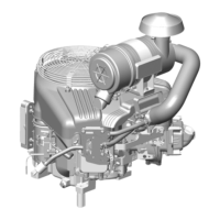
Adjust Valves
1. Before adjusting valves, make sure that the
Number 1 cylinder is at Top Dead Center
(TDC) - Compression Stroke (Figure 39).
Figure 39
2. Adjust valves and check (Figure 40).
• Valve Clearance (cold) IN and EX - 0.007
in. (0.18 mm).
• Torque adjusting screws and jam nuts
to values listed in Section 14 - Engine
Specifications.
 Loading...