19
2
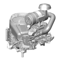
Figure 31
7. Install washers and torque nuts to values
listed in Section 14 - Engine Specifications.
NOTE: Make sure rocker adjustments studs are
seated in recessed end of push rods.
Install ignition coil bracket and ignition coils (Figure
32). Torque screws to values listed in Section 14 -
Engine Specifications.
8. Install ignition coil bracket and ignition coils
(Figure 32). Torque screws to values listed in
Section 14 - Engine Specifications.
Figure 32
9. Install intake manifold with new gasket. Install
governor link and spring (Figure 33). Torque
screws to values listed in Section 14 - Engine
Specifications.
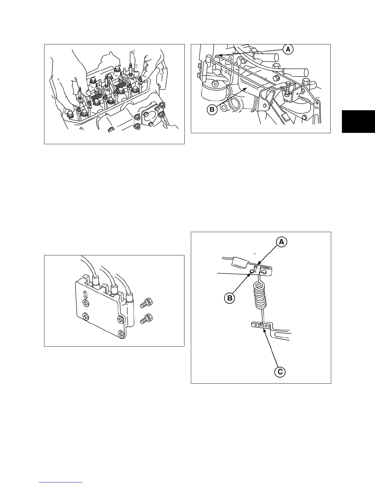
Figure 33
10. Insert governor spring into original hole in
governor lever.
NOTE: Normal spring position is in center hole in
the governor lever (Figure 34).
NOTE: Governor spring must be installed in correct
hole in governor control lever by engine model.
• Model 430400 - Top Hole
• Model 580400 - Bottom Hole
Figure 34
11. Install exhaust manifold with new gasket
(Figure 35). Torque screws to values listed in
Section 14 - Engine Specifications.
 Loading...