142
1212
Figure 18
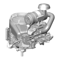
10. Install timing gear cover with new gasket.
Note position, length, and number of screws
(Figure 19). Torque screws to values listed in
Section 14 - Engine Specifications.
• M6 x 2.5 in. (M6 x 65 mm): 2 (A)
• M6 x 2.1 in. (M6 x 55 mm): 3 (B)
• M6 x 1.1 in. (M6 x 30 mm): 7 (C)
• M6 Nut: 2 (D)
Figure 19
11. Install crankshaft pulley with timing mark at
12 o’clock position (No. 1 cylinder) (Figure
19).
NOTE: Ensure alignment pin in crankshaft gear is
seated in hole in pulley.
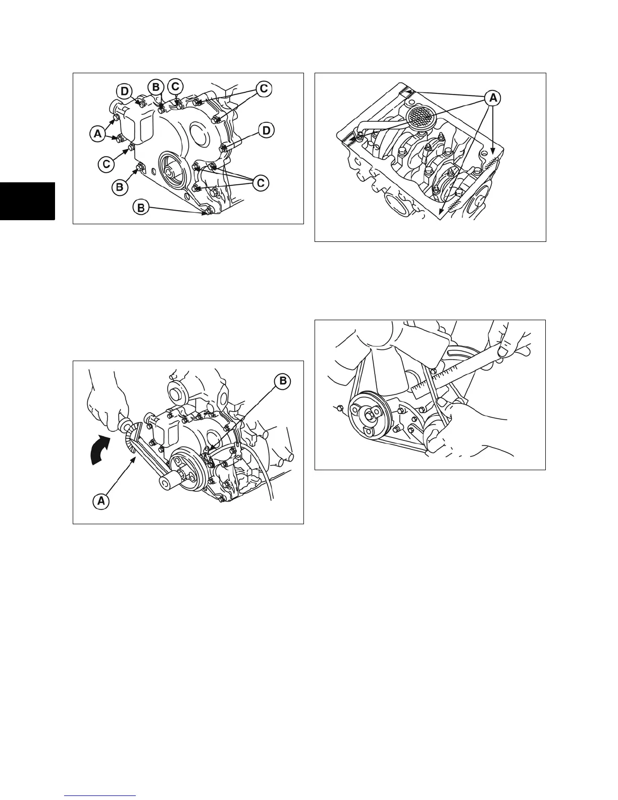
12. Remove flywheel holder (A, Figure 20) AND
install trigger assembly and wire (B).
Figure 20
13. Install oil pick-up tube and strainer with new
gasket.
14. Apply a small bead of Permatex® No. 2 or
other similar sealant (A, Figure 21).
Figure 21
15. Install oil pan with new gasket. Torque
screws and nuts to values shown in Section
14 - Engine Specifications.
16. Install V-belt and fan (if equipped).
17. Install governor lever (A, Figure 22) on to
governor shaft. Do not tighten governor nut
at this time.
18. Install governor link with spring (B).
 Loading...