1. Introduction VX TopCooler
Part Number: 606325 Rev. A
tocoolwafersinSEMI-standard100mmthrough200mmsizespriortofurtherprocessingor
reinsertionintoacassette.Thecoolingcycleinvolvesdischargingafixedquantityofgasintothe
closedcoolchamber,whichprovidesconductiveheattransferbetweenthegasandthechillplateto
coolthewafer.
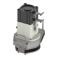
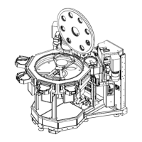
Withthedrop-indesignfabricatedfromaluminumandweighingonly18.1kg(40lb)theTopCooler
iseasytoinstallintothetransportchamber.TheTopCooleriseasytoservicewitharemovable
drop-inmechanismprovidingeasyaccesstothecoolplateforcleaning.See"Maintenanceand
Repair"onpage23forserviceprocedures.
See"Operation"onpage18foracompletedescriptionoftheoperationofthecooler.
Process Overview
Thecoolerwillprocesswafersplacedwithinitbycoolingthemforapredeterminedtime,which
bringsthewafertoapredeterminedtemperature.Wafersleftinthecoolerafterthepredetermined
timewillcontinuetocooltothetemperatureofthecooltray(typically20°C/68°F).Thiscooling
processistypicallyusedtolowerthewaferstoadesiredtemperaturepriortoinsertionintoaplastic
cassettetopreventdamagetothecassette.
Wafersenteringthemodulearesuspendedunderapoweroperatedlid,orpoppet.Aftertherobot
withdraws,thelidisclosed,isolatingthecoolchamberanddepositingthewaferonthecooltrayat
thebottomofthecoolchamber.Thechamberisthenfilledwithgas.Thissystemprovidescooling
from300°Cto70°Cinlessthan45sec.
Afterthecoolprocessiscomplete,thecoolchamberispumpeddownandthelidopens,raisingthe
wafertobepickedbytherobot.Oncecooled,thewafermayberemovedforcontinuedprocessing
orplacedinacassette.
NOTE: Thetimeandtemperaturerequirementsforcoolingmustbedeterminedbythe
userfortheirspecificapplication.
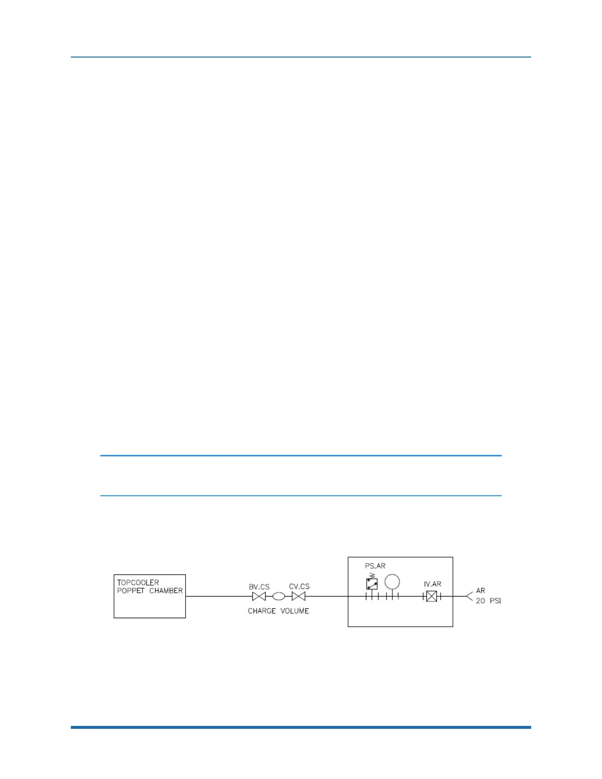
Block Diagram
Figure 1-2: TopCooler Block Diagram
8
Copyright © 2023, Brooks Automation, Inc.