3-69
Confidential
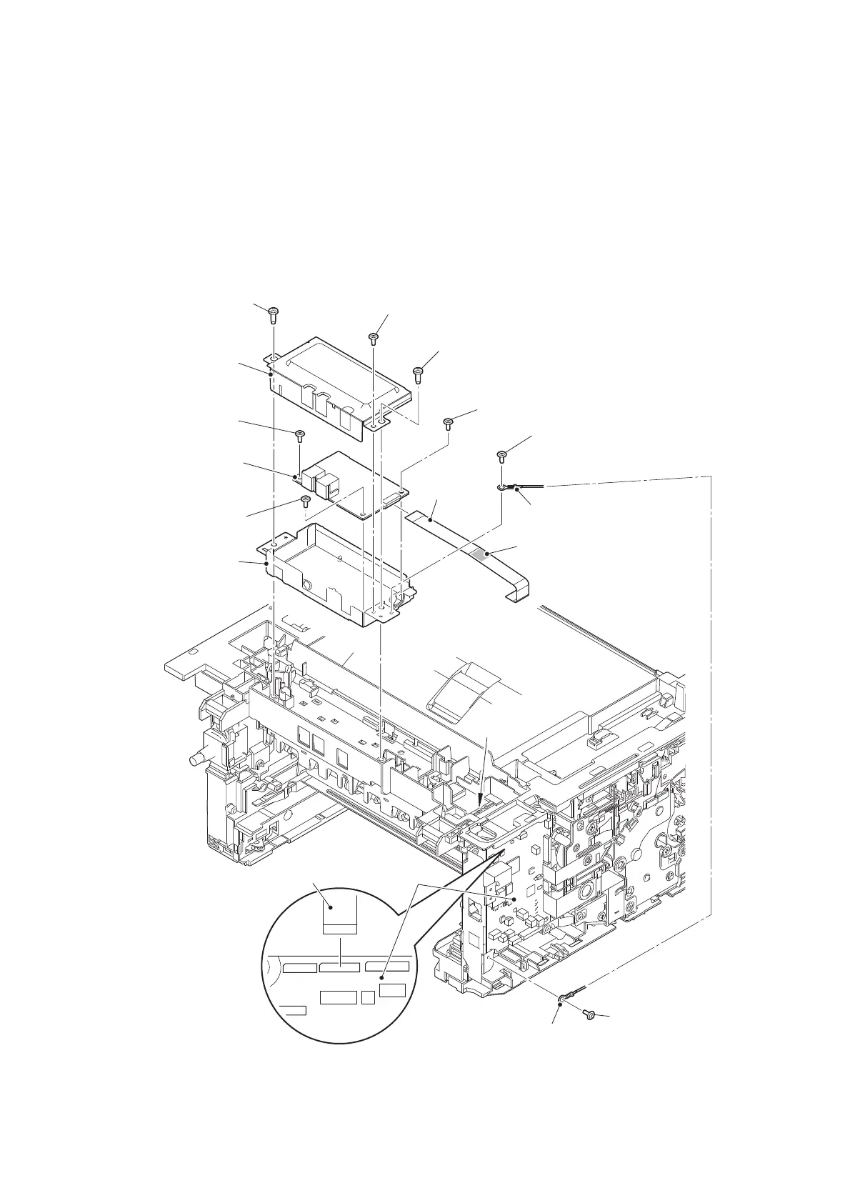
(2) Remove the two Screw cup M3x8 (black) screws, and release the Modem ground harness
main from the securing fixtures.
(3)
Disconnect the Modem flat cable from the Main PCB ASSY and the Modem PCB ASSY, and
remove it from the Double-sided tape to pull it out from the hole of the Joint cover ASSY.
(4) Remove the two Taptite bind B M4x12 screws to remove the Modem shield plate.
(5) Remove the Screw cup M3x8 (black) screw to remove the Modem shield cover from the
Modem shield plate.
(6) Remove the three Screw cup M3x8 (black) screws to remove the Modem PCB ASSY from
the Modem shield plate.
Fig. 3-62
Harness routing: Refer to “7. Modem PCB ASSY (LVPS side)”.
Taptite bind B M4x12
Main PCB ASSY
Screw cup M3x8 (black)
Taptite bind B M4x12
Screw cup M3x8 (black)
Screw cup M3x8 (black)
Modem ground harness main
Modem flat
cable
Modem shield
plate
Screw cup
M3x8 (black)
Modem PCB ASSY
Modem shield cover
Screw cup M3x8 (black)
Modem ground harness main
Modem flat cable
Screw cup M3x8
(black)
Double-sided tape
Hole of the Joint
cover ASSY
 Loading...