IV - 3
n
nn
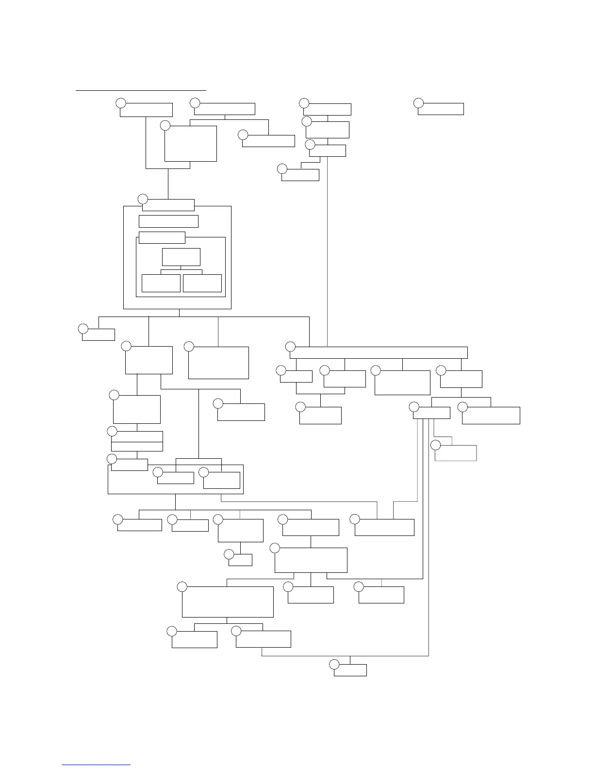
n Disassembly Order Flow
1.1
1.2
1.21
1.21
1.3
1.23
1.22
1.22 1.22
1.24
1.24
1.24
1.22
1.10
1.12
1.13
1.14
1.14
1.15
1.16
1.27
1.18 1.20
1.17
1.19
Fan
1.20
1.26
1.26
1.28
1.28
1.25
1.25
1.24
1.11
1.4
1.5
1.6
1.7
Document tray
ASSY
Upper rear cover
ADF unit and
document tray
open sensor
- Document
sensor PCB
(NOTE 1)
Scanner unit
Scanner top cover
Scanner base
- CCD unit
- CCD rail
- CCD
motor
- CCD flat
cable
1.8
Relay PCB
1.7
Control panel ASSY
- Control panel PCB
- FPC key
- LCD
1.9
Speaker
(NOTE 2)
(NOTE 1) On the document sensor PCB are these sensors
- Document front sensor
- Document rear sensor
On the harness support is a document tray open sensor.
(NOTE 2) On the scanner base is a CCD HP sensor.
(NOTE 3) On the heat-fixing unit are a jam sensor and heater thermistor.
(NOTE 4) The main PCB monitors the internal resistance of the in-casing
temperature sensor (thermistor) attached to the main chassis.
(NOTE 5) On the paper ejection sensor PCB is the paper ejection sensor
(photosensor).
(NOTE 6) On the engine PCB are these photosensors:
- Registration sensor
- Manual insertion sensor
- Cassette sensor
(NOTE 7) On the toner sensor (light-receiver) PCB is a light-sensitive
transistor.
(NOTE 8) On the toner sensor (LED) PCB are an LED and cover sensor
(photosensor).
Paper cassette
NCU PCB *
4
Lower rear cover
Access plates
R and F
NCU shield
(NOTE 4)
Bottom plate
Main PCB
Paper ejection
sensor PCB
Low-voltage power
supply PCB and
power inlet
Inner
insulation film
Engine PCB
High-voltage power
supply PCB
(NOTE 5)
(NOTE 6)
Bottom
insulation film
Paper pinch
rollers
Scanner mount
- Exit roller
VC cover, VC
bracket, and VC
connector PCB *
1
Front cover
Front sub cover *
2
Outer chute
Main cover
Switch cover *
3
Laser unit
Heat-fixing unit
- Heater roller
- FU lamp
(NOTE 3)
Drive gear ASSY
- Main motor ASSY
Develop joint and
front cover link (as cover
sensor actuator)
Paper feed
roller ASSY
Gears
(Inner gear 54, gear 45 set P/R,
gear 20 P/R, gear 40/54, gear 45
set F/R, and gear 20 F/R)
Paper pick-up
roller
Clutch levers and
cassette guide L
Solenoid
Toner sensor
(LED) PCB
(NOTE 8)
Toner sensor (light-
receiver) PCB
(NOTE 7)
*
1
Provided on models supporting video capture.
*
2
Provided on models not supporting video capture.
*
3
Provided on models not equipped with the power switch.
*
4
Provided on models supporting facsimile function.
*
5
Provided on models available with a 2nd paper cassette
(as an option).
2nd cassette
relay PCB *
5
Paper sub tray
and tray holder