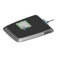
WORK STEP ILLUSTRATION / OTHER INFO
Connect the cable with the power connection.
On the GPM the LED should not light up, in other words OFF, see
7.3.1.1.
Make sure, that there are no foreign objects in the charging area.
Switch the power supply for the GPM on and check the residual
current device. If the GPM is supplied with mains voltage, then as
next step the LED signals the initialization of the foreign-/living
object detection, see
7.3.1.2.
Note the
availability of the user for
instruction in the use of the device and the
dangers that can emanate from the ICS.
Initialize the foreign-/living object detection:
Place an approx. 5cm large metallic object on the GPM and remove
it again after 10sec. If there is no vehicle in the vicinity which is
suitable for the ICS charging system, then the GPM flashes with the
appropriate pattern
7.3.1.3
The GPM now sends WLAN signals to vehicles in the reception
range, but is not yet connected with any vehicle.
If the vehicle with functional CPM is in the transmit range of the
installed GPM, then the vehicle must be made known to the GPM.
In
practice this takes place as follows
:
1.
In the vehicle display a list of all GPMs in the reception
range of the CPM is displayed.
2. The required GPM is selected
3. The password for the selected GPM is entered.
Once this step is successfully concluded, then the LED of the GPM
flashes with the pattern CONNECTED, see 7.3.1.4
Position the vehicle over the GPM, so that the CPM and GPM are
optimally overlaid. If the vehicle sends a request for charging and if
the request is successful, then you see that on the GPM by the LED
flashing pattern, see
7.3.1.5.
The preconditions for the start of the charging
process are OEM
-specific.
Wait a few minutes while the vehicle charges. Then place a suitable
foreign object (metallic, approx.
5cm diameter) in the space between
and CPM. The charging process should then be interrupted
and the LED on the GPM should flash, see
7.3.1.7
. After removing
the inserted object the charging process should be resumed, see
7.3.1.5
.
Remove the vehicle from the area in which charging is possible. The
status of the GPM should change to the status CONNECTED, see
7.3.1.4
, insofar as the vehicle is still sensed in the transmit range of
the GPM, or the GPM switches to the status NOT CONNECTED, if
the vehicle should not have any WLAN reception from the GPM, see
7.3.1.3
29
Operation Manual
Inductive Charging System
ICS115