1. General information
1.1
Application area
These operating instructions are intended for the water ring pumps of the 2BV2, 2BV5, 2BV6
series. The 2BV2 and 2BV5 pumps are single-stage pumps and are directly connected to the motor.
The 2BV6 series pumps are cantilevered and are supplied with an explosion-proof motor.
Before installing the equipment, be sure to familiarize the technician with the contents of
this manual, as it contains basic information on the installation, use and repair of the pump. It is
advisable to ensure that the technicians installing the pump have easy access to the manual
throughout the installation.
1.2
How it works
The 2BV pumps do not take up much space, are directly connected to the motor and are quite
compact. To install them, simply place them on a flat, horizontal surface and secure them. There is no
need to build a frame for them.
The 2BV series pumps operate on the water-ring principle. The impeller (impeller) in such a pump
is mounted eccentrically inside the working chamber - that is, its axis of rotation does not coincide with
the center of the chamber. After starting the pump, the working fluid
is spun by the impeller and, under the influence of centrifugal force, forms a liquid ring along the walls
of the working chamber. The impeller blades are partially immersed in the liquid. Since the impeller is
mounted eccentrically and the thickness of the water ring is the same around the entire perimeter of the
working chamber, the volume of air between a single pair of impeller blades and the working fluid
changes during each revolution.
When this volume increases, air is sucked in through the inlet valve. When it decreases, the gas is
pushed out through the exhaust valve.
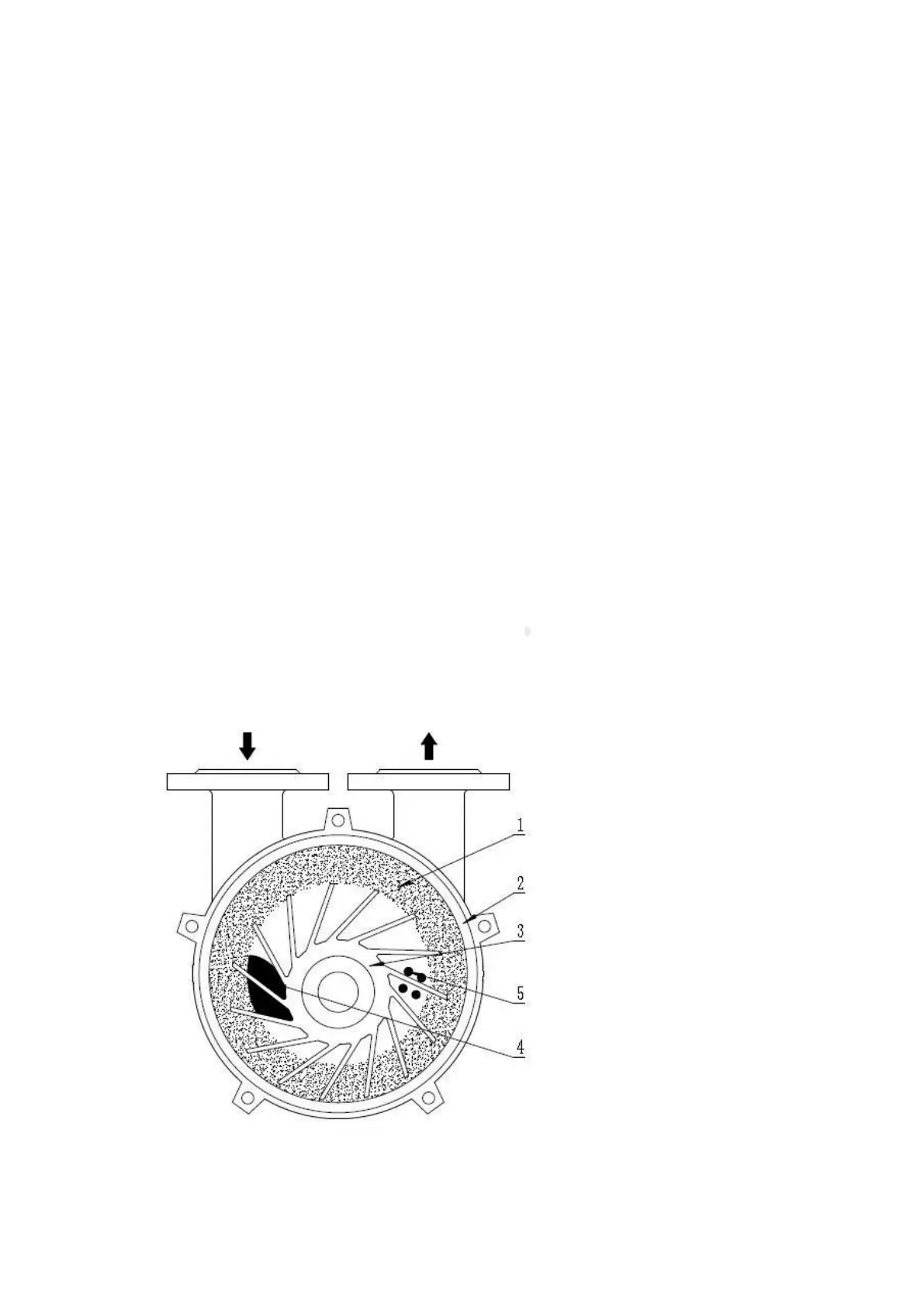
Figure 1 shows a schematic diagram of the water ring pump (view from the pump cover)
Figure 1:
1) working fluid
ring;
2) the wall of the
working
chamber;
3) impeller
(impeller);
4) air inlet;
5) air outlet.
 Loading...