Do you have a question about the Buckeye X80 and is the answer not in the manual?
Connects to computer with USB and is the lowest cost base option.
Connects to computer over Internet using cellular data plan.
Connects to computer with Ethernet using existing network.
Acts as a base with an SD card, no computer required.
Install software for Windows either from CD or online.
Follow chapter-specific instructions for PC, Cell, or Net Base.
Refer to Chapter 7 for camera registration procedures.
Refer to Chapter 8 for detailed camera configuration options.
Refer to Chapter 9 for guidance on camera placement and installation.
Connect the antenna to the PC Base unit for indoor use.
Ensure computer meets minimum requirements and connect via USB.
Launch the software and select the PCBase connection option.
Initiate the connection process from the software interface.
Finalize the PC Base connection setup in the software.
Ensure a cellular data plan is active before proceeding with setup.
Connect the AC/DC wall adapter or an external battery.
Use the provided cable to connect to a 12V marine battery.
Connect the specified Buckeye Cam solar charger if used.
Connect the battery pack to the Cell Base enclosure.
Attach the necessary antennas to the Cell Base unit.
Open the Cell Base housing to access internal components.
Power on the Cell Base by setting the toggle switch.
Monitor LED indicators for successful initialization.
Launch the software and select the Cell Base connection.
Input network details from the Cell Base Information Sheet.
Configure default settings for normal operation.
Activate Low Battery Detection for battery protection.
Adjust settings for connection monitoring and reconnection attempts.
Initiate the connection process from the software.
Finalize the Cell Base connection setup.
Securely close the Cell Base enclosure after setup.
Connect the power adapter pigtail to the AC/DC adapter.
Connect the power adapter to the Net Base unit.
Connect the power adapter to a suitable wall outlet.
Open the Net Base housing to access internal components.
Power on the Net Base by setting the toggle switch.
Connect the Net Base to the local network using an Ethernet cable.
Launch the software and select the Net Base connection.
Input the assigned IP address or domain name for the Net Base.
Provide the authentication code from the Net Base information sheet.
Configure connection monitoring and reconnection intervals.
Initiate the Net Base connection from the software.
Securely close the Net Base enclosure after setup.
Attach the antenna to the camera for signal transmission.
Install the battery, ensuring correct polarity for connection.
Secure the battery pack and connect it to the camera unit.
Prepare the camera for registration by checking its display status.
Access the device management feature within the software.
Register the camera by placing its icon in the network diagram.
Perform the registration process for each camera in the system.
Secure the camera enclosures after successful registration.
Click the camera icon in the network view to open its control panel.
Click the 'Settings' button from the Control Panel to adjust parameters.
Add date, time, temperature, or custom text to images.
Select image resolution or video format.
Set the time interval before the camera responds to another trigger.
Adjust the sensitivity of the motion detection system.
Determine how many pictures are taken per motion event.
Enable or disable the visual LED indicator for motion detection.
Configure the camera to be active or inactive at specific times.
Control the order in which transmitted pictures are sent.
Set X-Series Network Manager to automatically delete old pictures.
Secure the camera using the supplied strap or mounting bracket.
Install and connect the battery pack to the camera.
Verify Base is powered and camera is registered before proceeding.
Open enclosure and check LCD for "Signal to Base" status.
Secure the camera enclosure after checking signal.
Test motion detection by walking in front of the camera.
Fine-tune camera angle for desired detection range.
Apply the installation and testing process to all cameras.
Discusses omnidirectional antennas, transmission capabilities, and limitations.
Details omnidirectional antennas for 360° transmission, suitable for base or repeaters.
Describes directional antennas for focused transmission, providing highest gain.
Example illustrating how repeaters overcome line-of-sight obstructions.
Example showing repeaters to overcome range limitations.
Important considerations like transmission delays and antenna upgrades.
Ensure cameras are installed and have a signal to the base.
View the camera's current connection path using the NEXT button.
Use the CHANGE button to search for and select new routing devices.
Review a list of available devices for routing after a search.
Choose a specific camera (node) to route through using the ENTER button.
Verify the connection is established by checking for an "OK" confirmation.
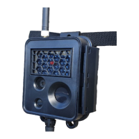
Identifies key components of the X80 camera unit.
Explains the purpose of the HOME, NEXT, CHANGE, and ENTER buttons.
Provides physical dimensions of the camera and its battery pack.
Lists technical details like picture format, video, motion detection, and RF range.
Attach the antenna to the camera for network communication.
Install the battery, observing correct polarity for the pack.
Secure the battery pack and connect it to the camera unit.
Prepare the camera for configuration by checking its display status.
Configure the camera to operate as a base station.
Allow the camera to restart after setting the base mode.
Apply initial setup steps to all cameras in the network.
Register other cameras to the configured Camera Base.
Obtain software from buckeyecam.com and save to an SD card.
Follow general camera installation steps from Chapter 9.
Solutions for problems connecting to a PC Base via Network Manager.
Troubleshooting steps for Cell Base connectivity problems.
Solutions for connecting to a Net Base with Network Manager.
Tips for improving signal when using standard antennas with a PC Base.
Advice for optimizing signal with directional antennas to a PC Base.
Solutions for improving signal from cameras to a Cell Base.
Access video guides for X-Series Network Manager online.
Information on uploading and viewing images via the LiveCam service.
Overview of compatible sensors, repeaters, and controllers in the X80 series.
Contact details for ATSI/Buckeye Cam for service and repairs.
Details the warranty period and conditions for X80 products.
| WDR | 120 dB |
|---|---|
| Ingress Protection | IP67 |
| Image Sensor | 1/2.8" Progressive Scan CMOS |
| Max. Resolution | 3840 x 2160 |
| Video Compression | H.265, H.264 |
| Storage | MicroSD card slot (up to 256GB) |
| Protocols | TCP/IP, RTSP, RTP, UDP, SMTP, FTP, DHCP, DNS, DDNS, NTP, UPnP, 802.1X, QoS |