2003 Buell P3: Electrical 7-15
HOME
REMOVAL
1. Remove seat. See 2.28 SEAT.
11WARNING1WARNING
To protect against shock and accidental start-up of vehi-
cle, disconnect the negative battery cable before proced-
ing. Inadequate safety precautions could result in death
or serious injury.
2. Disconnect negative battery cable from battery terminal.
3. Remove four screws and washers to detach windscreen
from mounting brackets. See 2.26 WINDSCREEN.
4. See Figure 7-14. Cut cable tie and disconnect ignition
key switch connector [33] from main wiring harness.
Note location of cable tie.
5. Remove two headlight bucket bolts and headlamp
bucket. See 7.17 HEADLAMP.
6. Remove two bolts and ignition key switch.
INSTALLATION
1. Apply LOCTITE THREADLOCKER 243 (Blue) to threads
of two ignition key switch bolts.
2. Install ignition key switch into hole and secure with two
bolts. Tighten bolts to 48-72 in-lbs (5-8 Nm).
3. See Figure 7-14. Attach ignition key switch connector
[33] to main wiring harness. Secure harness with cable
tie.
4. Install headlight bucket with two bolts. Tighten bolts to
12-14 ft-lbs (16-19 Nm).
5. Cable tie ignition key switch connector [33] to main wiring
harness.
6. Install four screws and washers to attach windscreen to
mounting brackets. See 2.26 WINDSCREEN.
7. Install negative battery cable to battery terminal. Tighten
fastener to 60-96 in-lbs (6.8-10.8 Nm).
After installing seat, pull upward on front of seat to be
sure it is locked in position. If seat is loose, it could shift
during vehicle operation and startle the rider, causing
loss of control of vehicle and result in death or serious
injury.
8. Install seat. See 2.28 SEAT.
Check for proper headlamp operation before riding
motorcycle. Visibility is a major concern for motorcy-
clists. Failure to have proper headlamp operation could
result in death or serious injury.
9. Check ignition key switch for proper operation. If opera-
tion fails, reread procedure and verify that all steps were
performed.
a. Turn ignition key switch to OFF. Check all functions
listed in Table 7-11.
b. Turn ignition key switch to IGN. Start motorcycle.
See Section 4.
c. Turn ignition key switch to LOCK.
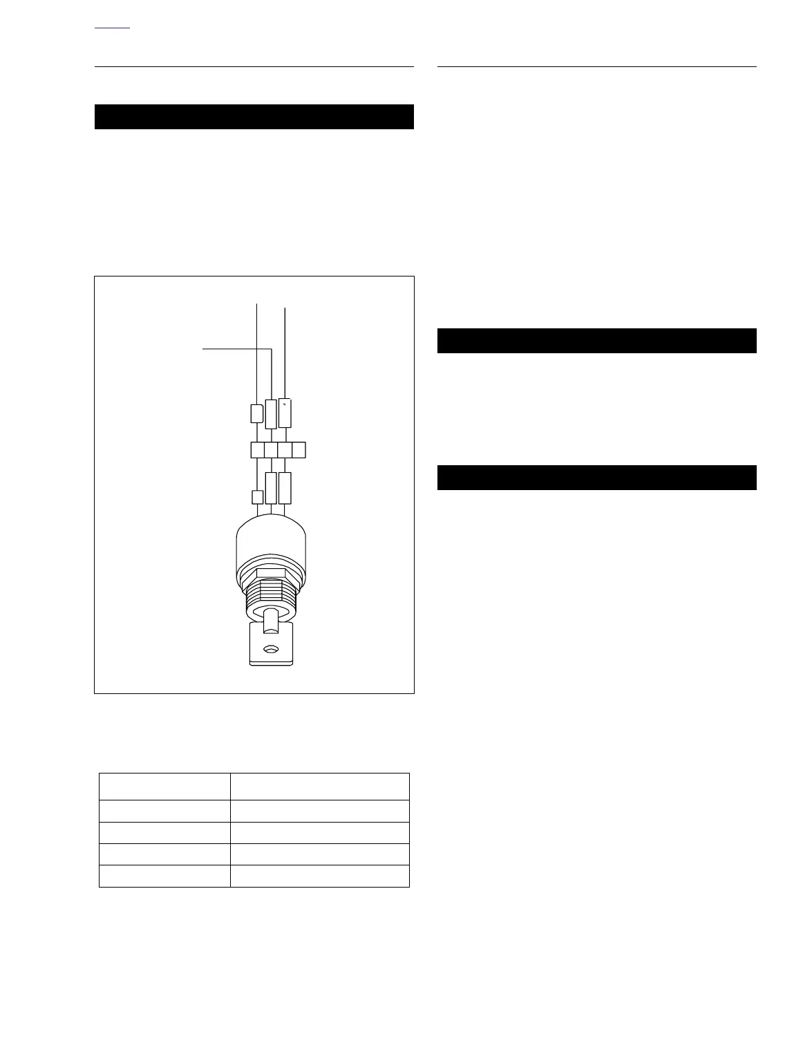
Figure 7-14. Ignition Key Switch Connector [33]
Table 7-13. Ignition Switch Connector [33]
[33] WIRE TERMINATION
A Master circuit breaker
BAccessories fuse in fuse block
CIgnition fuse in fuse block
D Empty
/BRK
R
/BR
R
K
/
RGY
A
B
C
D
/
RGY
a0284x7x
 Loading...


