7-24 2003 Buell P3: Electrical
HOME
Ignition Coil Secondary Circuit Test
1. Remove ignition coil.
2. Set ohmmeter scale to RX1K.
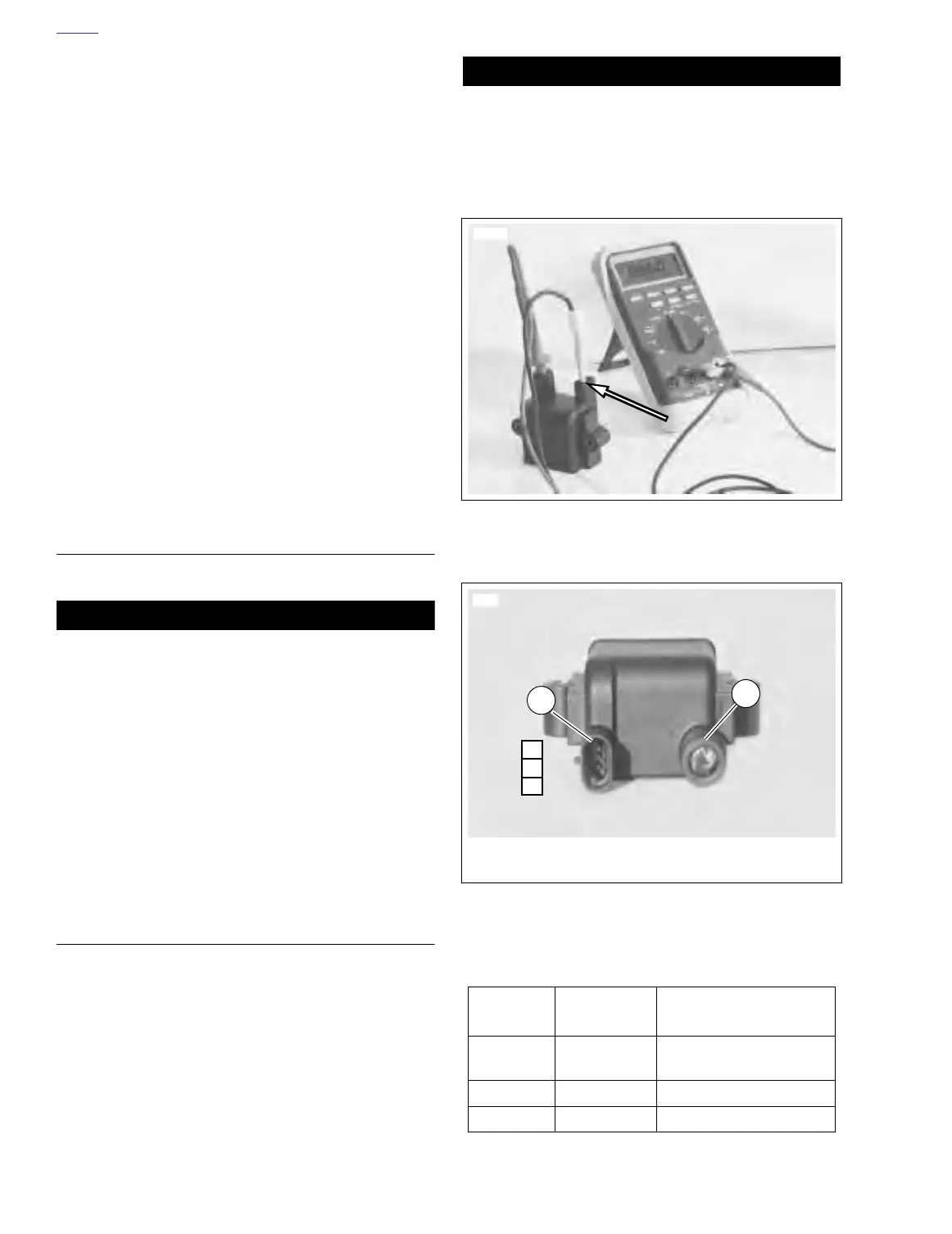
3. See Figure 7-26. Using harness connector adaptor kit
(HD-41404) gray female probes and patch cord, place
multimeter wires on secondary coil windings. See 7.9
IGNITION COIL.
4. Check for secondary coil winding resistance.
a. Normal resistance range is 7,720-9,440 ohms.
b. See Te st Results if resistance is not within normal
operating range.
Test Results
1. A low resistance value indicates a short in the coil wind-
ing. Replace coil.
2. A high resistance value might indicate that there is some
corrosion/oxidation of the coil terminals. Clean the termi-
nals and repeat resistance test. If resistance is still high
after cleaning terminals, replace coil.
3. An infinite ohms (∞ or no continuity) resistance value
indicates an open circuit (a break in the coil winding).
Replace coil.
REMOVAL
1. Remove seat. See 2.28 SEAT.
11WARNING1WARNING
To protect against shock and accidental start-up of vehi-
cle, disconnect the negative battery cable before proced-
ing. Inadequate safety precautions could result in death
or serious injury.
2. Disconnect negative battery cable from battery terminal.
3. Remove fuel tank cover. See 4.2 FUEL TANK COVER/
FUEL TANK.
4. Remove left side cover.
5. See Figure 7-24. Disconnect spark plug cable from coil
plug post.
6. See Figure 7-27. Disconnect coil connector [83].
7. Remove two screws and washers and coil.
INSTALLATION
1. See Figure 7-24. Apply LOCTITE 243 (Blue) to threads
of two mounting screws.
2. Attach coil to frame with screws and washers (1). Tighten
to 48-72 in-lbs (5-8 Nm).
3. Attach coil connector [83].
4. Connect spark plug cable to ignition coil.
5. Attach left side cover.
6. Install negative battery cable to battery terminal. Tighten
fastener to 60-96 in-lbs (7-11 Nm).
7. Install fuel tank cover. See 4.2 FUEL TANK COVER/
FUEL TANK.
11WARNING1WARNING
After installing seat, pull upward on front of seat to be
sure it is locked in position. If seat is loose, it could shift
during vehicle operation and startle the rider, causing
loss of control of vehicle and death or serious injury.
8. Install seat. See 2.28 SEAT.
Figure 7-26. Ignition Coil Secondary Resistance Test at
Terminal C
Figure 7-27. Coil Viewed From Bottom
Table 7-16. Coil Connector [83]
CHAMBER
NUMBER
WIRE COLOR FUNCTION
A
White/Black (+) To Right Handlebar
Switch
BPink (-) To Ignition Module
CBlack Ground
7798
7799
1. Connector [83A], with terminals C,B and A
2. Spark plug post
C
B
A
1
2
 Loading...


