16
Configuration and Function
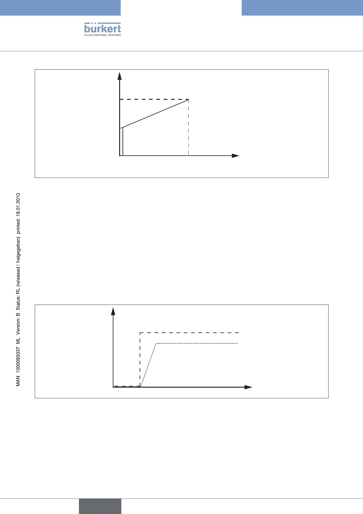
Standard signal
Figure 7: Current over standard signal
The working range can also be scaled using the key values I
1
and I
2
in such a way that only a part of the full opening
of the valve is covered over the full range of the standard signal. In particular the flow rate range can be limited to a
smaller value than the valve would permit under the given pressure conditions.
The zero point cut-off guarantees the leak-tight closing of the valve at input signals below a given threshold of the
input signal (e.g. < 2 % of the limit value). In this case at values below this threshold, the coil current is set - in
deviation from the line shown in Figure 7: Current over standard signal - to zero so that the full force of the return
spring of the valve acts as a closing force.
The zero point cut-off can be optionally activated or deactivated.
A serves to attenuate sudden changes in the input signal and to transform them into an adjustable ramp
(time constant 0 to 10 s) (see Figure 8: Ramp function). This is expedient for applications in which sudden changes
in the fluidic controlled variable are undesirable. The ramps can be set separately for positive and negative jumps.
The frequency of the PWM signal must be adapted to the valve used.
Standard signal
Current
Figure 8: Ramp function
The with superordinate controllers (PC’s, etc.) is possible via RS232 or RS485 interfaces
using auxiliary modules (see 11.1.Ordering charts: Device variants).