13
Installation
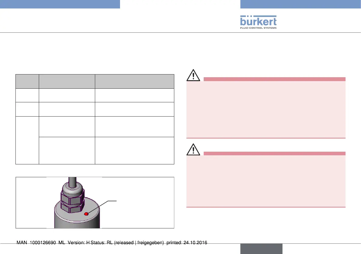
7.2 Display elements of the rotating
Remote Sensor
An LED on the upper side of the sensor housing is used to indicate
the sensor mode.
Status
LED
Display Remedial action
off No operating voltage Check supply voltage, connection.
on
(green)
Ready for operation -
on
(red)
Starting phase
(during the acceleration
phase – booting)
-
Sensor error
Switch off the operating voltage
and switch it on again. The sensor
is defective if the display con-
tinues to show “Sensor error”.
Tab. 2: LED display elements; rotating Remote Sensor
Status
LED
Fig. 7: LED display elements; rotating Remote Sensor
8 INSTALLATION
8.1 Safety instructions
DANGER!
Risk of injury from high pressure in the equipment/device.
▶ Before working on equipment or device, switch off the pressure
and deaerate/drain lines.
Risk of electric shock.
▶ Before working on equipment or device, switch off the power
supply and secure to prevent reactivation.
▶ Observe applicable accident prevention and safety regulations
for electrical equipment.
WARNING!
Risk of injury from improper installation.
▶ Installation may be carried out by authorized technicians only
and with the appropriate tools.
Risk of injury from unintentional activation of the system and
an uncontrolled restart.
▶ Secure system from unintentional activation.
▶ Following assembly, ensure a controlled restart.
english
Type 8798