33
Electrical installation
10.2 Electrical connection to the
positioner Type 8791 or Type
8792/8793
Procedure:
→ If necessary, shorten the cable of the Remote Sensor and connect
it to the M12 cable gland on the positioner Type 8791 or Type
8792/8793.
→ Connect the 4 wires of the cable, as described in “Tab. 6” and
in the operating instructions of the positioner Type 8791 or Type
8792/8793, to the appropriate terminals (Chapter "Terminal
assignment for external position sensor" in the operating instruction
of Type 8791 or Type 8792/8793).
Terminal Wire color Configuration External circuit
8791 or
8792/8793
for cable type
1 2
1 white black Supply
sensor -
S –
2 brown Supply
sensor +
S +
3 yellow orange Serial interface
B cable
B
4 green red Serial interface A
cable
A
Tab. 6: Wire color - configuration with screw-type terminals
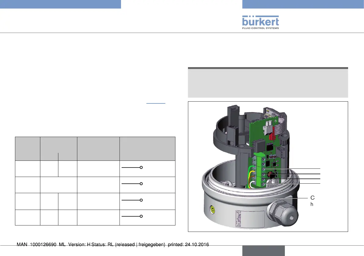
10.2.1 Terminal configuration linear
Remote Sensor
NOTE!
Breakage of the pneumatic connection pieces due to rota-
tional impact.
▶ When unscrewing the body casing, do not hold the actuator of
the process valve but the connection housing.
4
3
2
1
Connection
housing
Fig. 34: Terminal configuration linear Remote Sensor
english
Type 8798