34
Start-Up
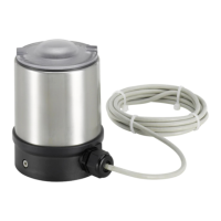
10.3 Electrical connection of the
rotating Remote Sensor to the
positioner Type 8791 or Type
8792/8793
→ If necessary, shorten the cable of the Remote Sensor or extend it
to a maximum of 10 m and connect it to the designated M12 cable
gland on the positioner Type 8791 or Type 8792/8793.
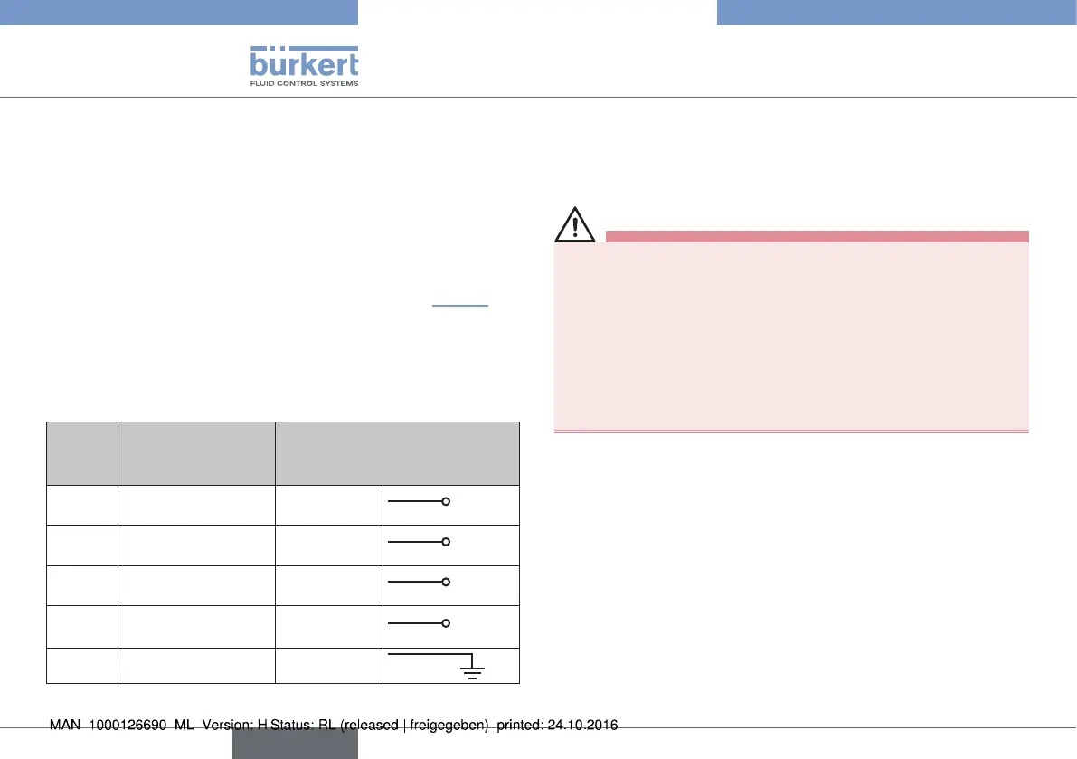
→ Connect the 4 wires of the cable, as described in “Tab. 7” and
in the operating instructions of the positioner Type 8791 or Type
8792/8793, to the appropriate terminals.
→ For potential equalization, connect the shield of the cable to the
grounding connection in the terminal compartment of the position
controller.
Wire
color
Configuration External circuit
8798 8791 or
8792/8793
brown Supply sensor +
Brown (BN)
S +
white Supply sensor –
White (WH)
S –
grey Serial interface
A cable
Grey (GY)
A
pink Serial interface
B cable
Pink (PK)
B
black Shielding
Black (BK)
Tab. 7: Wire colors and configuration; rotating Remote Sensor
11 START-UP
11.1 Safety instructions
WARNING!
Risk of injury from improper operation.
Improper operation may result in injuries as well as damage to the
device and the area around it.
▶ Before start-up, ensure that the operating personnel are familiar
with and completely understand the contents of the operating
instructions.
▶ Observe the safety instructions and intended use.
▶ Only adequately trained personnel may operate the equipment/
the device.
No separate steps for starting up are necessary for the Remote
Sensor Type 8798.
→ Carry out the steps outlined for starting up in the operating
instructions of the positioner (Chapter "Start-up" in the operating
instructions of Type 8791 or Type 8792/8793).
english
Type 8798