14
Installation
8.2 Installation of the linear Remote
Sensor Type 8798
8.2.1 Attachment to process valves with
internal air supply (series 2103,
2300 and 2301)
NOTE!
When mounting on process valves with a welded body, follow
the installation instructions in the operating instructions for
the process valve.
Procedure:
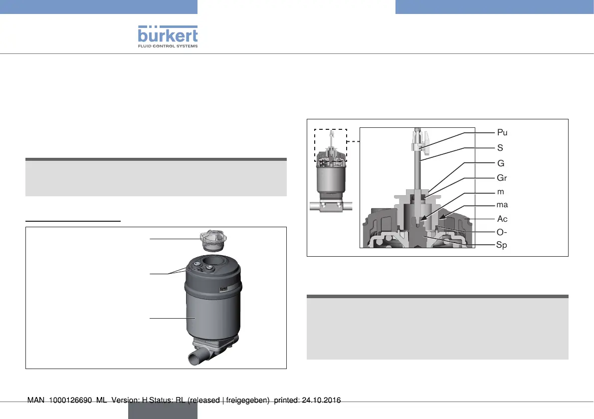
1. Install switch spindle
Transparent cap
Actuator
Pilot air ports
(plug-in hose connectors with
collets or threaded bushings)
Fig. 8: Installation of linear Remote Sensor, series 2103, 2300
and 2301
→ Unscrew the transparent cap on the actuator and unscrew the
position display (yellow cap) on the spindle extension (if present).
→ For version with plug-in hose connector, remove the collets
(white nozzles) from both pilot air ports (if present).
O-ring
Spindle extension
Guide element
Actuator cover
Groove ring
Puck
Switch spindle
max. 5 Nm
max. 1 Nm
Fig. 9: Installation of the switch spindle, series 2103, 2300 and
2301
NOTE!
Improper installation may damage the groove ring in the
guide element.
The groove ring is already be pre-assembled in the guide element
and must be “locked into position” in the undercut.
▶ When installing the switch spindle, do not damage the groove ring.
→ Push the switch spindle through the guide element.
english
Type 8798