30
Fluid installation
The length of this control line should be adapted to the actuator
size because the clearance volumes caused by the control
line can have a negative influence on the control properties.
The following is the case: the smaller the actuator, the more
sensitively the control system reacts to the length of the
pneumatic control line.
Procedure:
Control functions A and B (single-acting actuators):
→ Connect the working connection A1 or A2
4)
of the positioner
Type 8791 or Type 8792/8793 to the connection (1) using a
hose.
→ Attach the exhaust airline or a silencer to the connection (3
1
).
4)
in line with desired safety position (see operating instructions Type 8791
or Type 8792/8793)
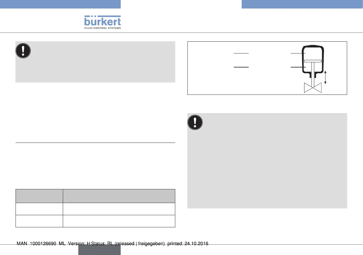
Control function I (double-acting actuators):
→ Connect working connections A1 and A2 to the respective
chambers of the Remote Sensor.
Connection for
Remote Sensor
Actuator
3
1
upper chamber of the actuator
1 lower chamber of the actuator
Tab. 5: Pneumatic connection - control function I
up
down
lower chamberConnection 1
upper chamberConnection 3
Fig. 32: Pneumatic connection - control function I
Caution: (Exhaust air concept):
In compliance with degree of protection IP67, an exhaust
air line must be installed in the dry area (control function A
and B).
Keep the adjacent supply pressure always at least 0.5 –
1 bar above the pressure which is required to move the
actuator to its end position. This ensures that the control
behavior is not extremely negatively affected in the upper
stroke range on account of too little pressure difference.
During operation keep the fluctuations of the pressure supply
as low as possible (max. ±10 %). If fluctuations are greater,
the control parameters measured with the X.TUNE function
are not optimum.
english
Type 8798