27
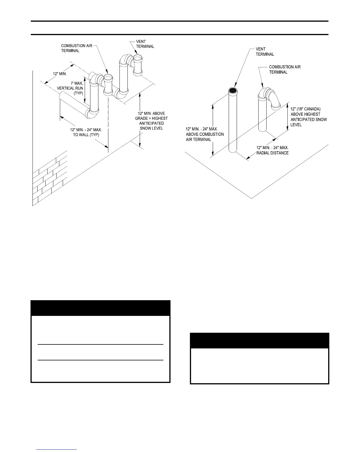
• Install maximum vertical run of seven (7)
feet of Schedule 40 PVC vent pipe. See
Figure 10.
• At top of vent pipe length install another
PVC 90° elbow so that elbow leg is
opposite the building’s exterior surface.
• Install Rodent Screen and Combustion
Air Terminal (supplied with boiler), see
Figure 9 for appropriate conguration.
• Brace exterior piping if required.
WARNING
All CPVC supplied with the vent kit must be
used prior to connection of the vent system to
this terminal. If the vent system is too short
to permit this, do not use this terminal.
Do not operate boiler without the rain cap in
place.
Methods of securing and sealing terminals
to the outside wall must not restrain the
thermal expansion of the vent pipe.
7.
Vertical Vent Termination
a. Standard Two-Pipe Termination
Refer to Figures 7, 9, 11 and 12.
Figure 11: Direct Vent - Vertical Terminations
Figure 10: Direct Vent - Optional Sidewall
Snorkel Terminations
i. Vent Piping
•
Install re stops where vent passes
through oors, ceilings or framed walls.
The re stop must close the opening
between the vent pipe and the structure.
• Whenever possible, install vent straight
through the roof. Refer to Figures 11 and
12.
- Size roof opening to maintain
minimum clearance of 1" from
combustible materials.
- Extend vent pipe to maintain minimum
vertical and horizontal distance of
twelve (12) inches from roof surface.
additional vertical distance for
expected snow accumulation. Provide
brace as required.
CAUTION
Vertical venting and combustion air roof
penetrations (where applicable) require the use
of roof ashing and storm collar, which are not
supplied with boiler, to prevent moisture from
entering the structure.
- Install storm collar on vent pipe
immediately above ashing. Apply
Dow Corning Silastic 732 RTV
Sealant between vent pipe and storm
collar to provide weather-tight seal.
IV. Venting (continued)