26
use is optional for non-combustible wall.
Insert thimble from wall from outside.
Secure outside ange to wall with nails
or screws, and seal ID, OD and vent
holes with sealant material. Install inside
ange to inside wall, secure with nails or
screws, and seal with sealant material.
• For noncombustible wall application
when thimble is not used, size opening
such that a minimal clearance is
obtained.
See Figure 7.
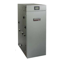
• Install Rodent Screen and Vent Terminal
(supplied with boiler), see Figure 9 for
appropriate conguration.
• Apply sealant between vent pipe and
opening/thimble to provide weather-tight
seal. Sealant should not restrain the
expansion of the vent pipe.
Figure 9: Rodent Screen Installation
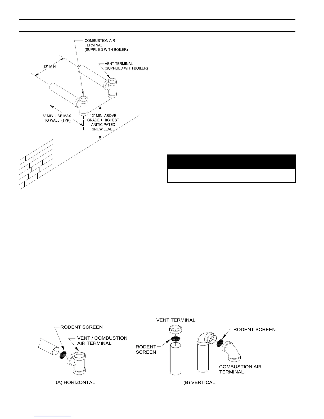
Figure 8 : Direct Vent - Sidewall Terminations
ii. Combustion Air Piping
•
Do not exceed maximum combustion air
length. Refer to Table 7.
• Size combustion air wall penetration to
allow easy insertion of combustion air
piping.
• Install Rodent Screen and Combustion
Air Terminal (supplied with boiler), see
Figure 9 for appropriate conguration.
• Apply sealant between vent pipe and
opening to provide weather
-tight seal.
b. Optional
Two-Pipe Snorkel Termination
Refer to Figures 7, 9 and 10.
This installation will allow a maximum of
seven (7) feet vertical exterior run of the vent/
combustion air piping to be installed on the
CPVC/PVC horizontal venting application.
NOTICE
Exterior run to be included in equivalent vent/
combustion air lengths.
i. Vent Piping
•
After penetrating wall, install a Schedule
40 PVC 90° elbow so that the elbow leg
is in the up direction.
• Install maximum vertical run of seven (7)
feet of Schedule 40 PVC vent pipe. See
Figure 10.
• At top of vent pipe length install another
PVC 90° elbow so that elbow leg is
opposite the building’s exterior surface.
• Install Rodent Screen and Vent Terminal
(supplied with boiler), see Figure 9 for
appropriate conguration.
• Brace exterior piping if required.
ii. Combustion Air Piping
• After penetrating wall, install a Schedule
40 PVC 90
o
elbow so that elbow leg is in
the up direction.
IV. Venting (continued)