C-Nav Hardware Reference Guide
78
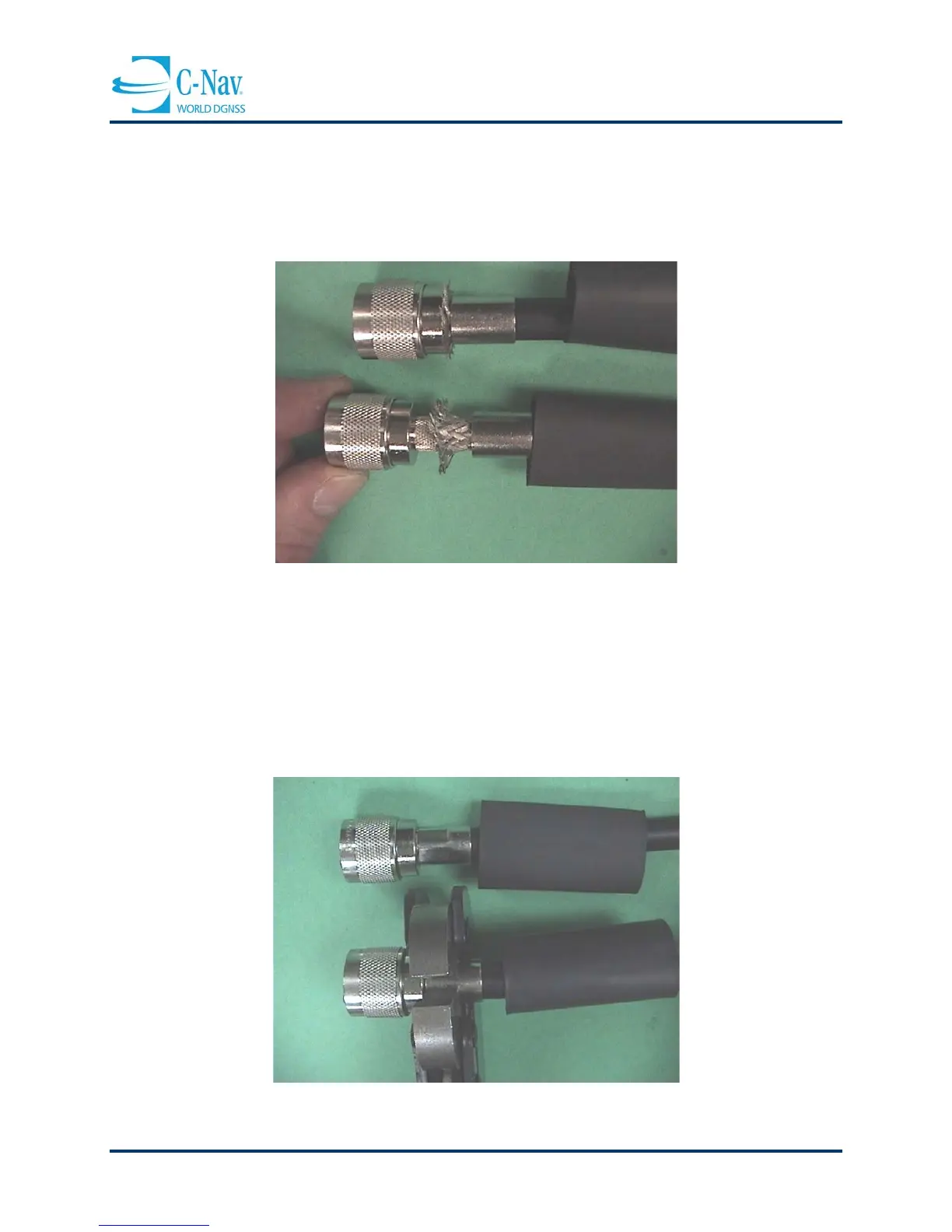
7. Remove the shim and slide the connector over the pin. Once the connector has
been pushed all the way on so that the connector bottoms out onto the core,
slide the ferrule over the braid, making an impression in the braid at the point that
it protrudes between the ferrule and the connector. Trim the braid at this
impression with scissors.
Figure 5-7: Connector Installation
8. Make sure that the connector is bottomed. Bring the ferrule all the way up to the
back of the connector. Check the pin height with a pin gauge. Crimp the ferrule
close to the connector with a crimping tool. DO NOT CRIMP TWICE. A second
crimp further back on the ferrule will end up compressing the core and cause
degradation of performance. Slide the boot up to the back of the coupling nut and
shrink with a heat gun until a lip of adhesive can be seen at both ends of the
boot.
Figure 5-8: Ferrule Crimping