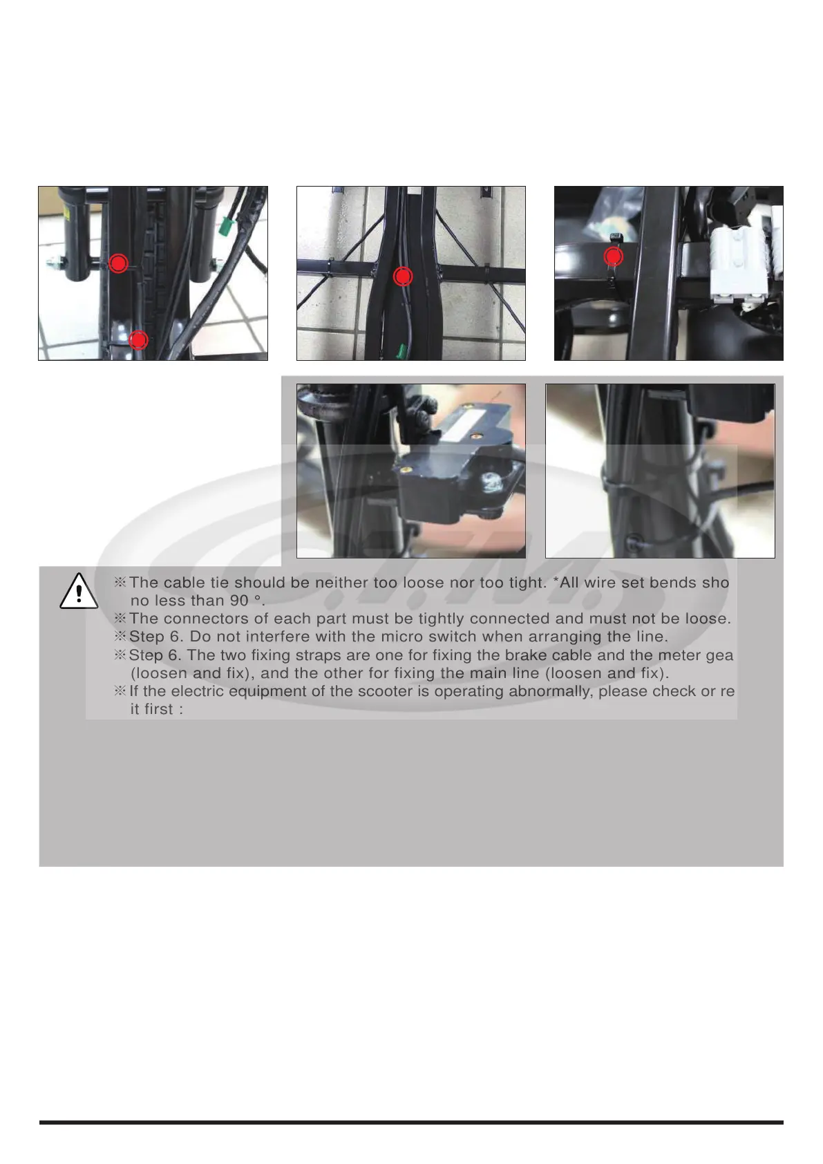
※The cable tie should be neither too loose nor too tight. *All wire set bends should be
no less than 90 °.
※The connectors of each part must be tightly connected and must not be loose.
※Step 6. Do not interfere with the micro switch when arranging the line.
※Step 6. The two fixing straps are one for fixing the brake cable and the meter gear wire
(loosen and fix), and the other for fixing the main line (loosen and fix).
※If the electric equipment of the scooter is operating abnormally, please check or replace
it first :
1.Corresponding electrical connectors and equipment.
2.Upper control panel connector and equipment.
3.Main controller connector and equipment. If there is no abnormality, check the main
line and replace it with a new one.
※When the main line is reassembled or replaced, be sure to retie the cut-open fixing straps
as described above and fix it without tightening too tightly.
※The brake cable trace is on the right side of the scooter, and the main line is on the left
side; the main line must be fixed on the left side of the frame to prevent interference.
43
6.Cut the main trace strap on the left side of the front frame (2pcs).
7.The main line passes through the groove at the bottom of the frame. Please pull it directly away
from the groove.
8.The main line extends to the top of the rear frame and cuts the strap (x 1pcs).
※The entire brake cable can now be removed.
※Please follow the above steps in reverse for reassembly and replacement.