EasyManuals Logo

Cardinal 212 Series User Manual

Cardinal 212 Series
154 pages
To Next Page IconTo Next Page
To Previous Page IconTo Previous Page
Page #37 background imageLoading...
Page #37 background image
212/212X Installation & Technical
8200-M639-O1 Rev D 09/14
Page 29
CAUTION! Disconnect any external load cell
power supply before connecting load cells to the
indicator. Failure to do so will result in permanent
damage to the indicator.
Scale Cable Connections
Scale Connector Wiring
Pin No.
Description
A
- SIGNAL
B
+ EXCITATION
C
+ SIGNAL
D
- EXCITATION
E
GND = SHIELD
(Connect the load cell
cable shield wire here).
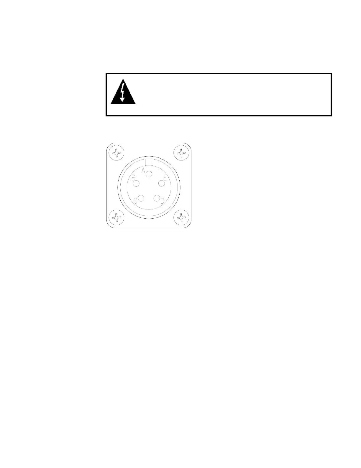
Figure No. 9
Figure No. 9 above is the 5-pin Scale connector as viewed from the
bottom of the indicator.
Connect each of the scale cable wires to the 5-pin scale connector. Note
that the scale connectors on the indicator identify the connector pins.

Table of Contents

Questions and Answers:

Question and Answer IconNeed help?

Do you have a question about the Cardinal 212 Series and is the answer not in the manual?

Cardinal 212 Series Specifications

General IconGeneral
BrandCardinal
Model212 Series
CategoryMeasuring Instruments
LanguageEnglish

Related product manuals