Do you have a question about the Cardinal 190 and is the answer not in the manual?
Notice regarding all rights reserved for manual content.
Statement of seller's liability and accuracy of manual information.
General safety and handling precautions for the indicator.
Environmental disposal guidelines for the electronic device.
Requirements for preparing the installation environment for optimal indicator performance.
Operating temperature, humidity, and placement guidelines for the indicator.
Specifies power requirements and safe electrical connections for the indicator.
Guidance on preventing electrical noise interference for stable operation.
Recommendations to reduce transient voltage surges affecting the indicator.
Details on P3 I/O connections, including input/output functions.
Details on P2 power connections for the indicator.
Information on the calibration inhibit jumper and its function.
Setting the primary weighing units (e.g., pounds, kilograms).
Configuring the interval setting for weight display resolution.
Setting the number of decimal places for weight display.
Setting the maximum capacity of the scale.
Setting the secondary weighing units.
Configuring the range for automatic zero tracking.
Setting the zero range limit.
Enabling or disabling automatic re-zero on power-up.
Selecting the time format (12-hour or 24-hour).
Configuring digital input functions and transitions.
Configuring digital output states for presets or checkweigher.
Configuring the sleep mode to conserve battery power.
Configuring the auto-shutoff feature to turn off the indicator.
Setting to indicate if a battery pack is installed.
Setting for analog to digital filtering configuration.
Prompt to confirm analog to digital filtering setup.
Configuring digital filtering parameters.
Setting the filter level from 1 to 99.
Setting the break range for filtering.
Configuring the sample rate for data acquisition.
Setting the motion range for stability detection.
Configuring the stable count for weight stability.
Third calibration weight step.
Fourth calibration weight step.
Fifth and final calibration weight step.
Initial prompt for serial input/output configuration.
Prompt to enable or skip serial input/output setup.
Configuring the serial interface baud rate.
Configuring the serial interface parity setting.
Enabling or disabling continuous output on the serial interface.
Selecting the format for continuous serial output.
Initial prompt for print tab settings configuration.
Prompt to enable or skip print tab settings.
Selecting the serial interface for printing.
Setting the print location for time data.
Setting the print location for date data.
Setting the print location for gross weight.
Setting the print location for tare weight.
Setting the print location for net weight.
Setting print location for gross weight accumulator.
Setting print location for net weight accumulator.
Setting print location for piece count.
Configuring data format termination for serial output.
Setting the number of line feeds after printing.
Initial prompt for fine span adjustment.
Prompt to confirm fine span adjustment.
Initial prompt for high resolution weight display.
Prompt to confirm high resolution weight display.
Initial prompt for key lockout feature.
Prompt to enable or skip key lockout feature.
Configuring the lockout status of the ZERO, TARE, and NET/GROSS keys.
Configuring the lockout status of the UNITS/ key.
Configuring the lockout status of the Fn/ key.
Configuring the lockout status of the PRINT key.
Configuring the lockout status of the ON/OFF key.
Initial prompt for options setup.
Prompt to enable or skip options setup.
Selecting the installed option card.
Configuring the baud rate for optional serial interfaces.
Initial prompt for function setup.
Prompt to enable or skip function setup.
Enabling and configuring Hold, Count, and Time/Date functions.
Enabling and configuring the Peak Hold function.
Enabling and configuring the Checkweigher function.
Enabling and configuring the Live Weight function.
Enabling and configuring the Weight Accumulation function.
Initial prompt for display backlight color setup.
Prompt to enable or skip display backlight color setup.
Setting the default display backlight color.
Setting backlight colors for Checkweigher 'Under' and 'Accept' statuses.
Setting backlight color for Checkweigher 'Over' status.
Description of standard key functions on the indicator keypad.
Enabling and configuring the Hold function.
Enabling and configuring the Count function.
Enabling and configuring time and date settings.
Enabling and configuring the Peak Hold function.
Enabling and configuring the Checkweigher function.
Enabling and configuring the Live Weight function.
Enabling and configuring the Weight Accumulation function.
Configuring display backlight colors for normal operation and checkweigher.
Selecting print formats for tickets.
Command to request displayed weight in Scoreboard format.
Command to request displayed weight in SMA format.
Command to zero the scale.
Command to set the scale to tare.
Command to return the tare weight.
Command to clear the scale tare weight.
Command to continuously repeat displayed weight.
Command to get the first line of scale information.
Command to scroll scale information.
Command to retrieve scale information.
Command to scroll scale information details.
Command to invoke scale diagnostics.
Command to abort current operations.
Response when an unrecognized command is received.
Troubleshooting guide for common indicator problems.
Steps to access and view event counters.
Identification and listing of parts for the front sub-assembly.
Specifics on AC wiring connections, including diagrams.
Illustration of P2 wiring when the 190-DAC option card is installed.
Information on available 190DC power options.
List of items included in the BP190 optional battery pack.
Technical specifications for the BP190 battery pack.
Explanation of the traffic control feature for the 190A.
Setup procedures for enabling axle weighing mode.
Configuring the scale as an automatic or standard axle weigher.
Setting the threshold weight for traffic control.
Setting the delay for the stoplight signal.
Setting the total delay before automatic print.
Wiring details for outputs and traffic control.
Selecting the format for continuous output.
Format for continuous output to Cardinal SB500 with traffic control.
Wiring details for the serial option card P4.
How to operate the 190-RS232 option card.
Technical specifications for the 190-RS232 option.
Description of status and diagnostic LEDs on the RS232 card.
Wiring details for the serial option card P4.
Initial prompt for options setup.
Prompt to enable or skip options setup.
Selecting the installed option card.
Configuring the baud rate for optional serial interfaces.
Key features of the 190-IP option card.
Description of status and diagnostic LEDs for the IP card.
Initial prompt for options setup.
Prompt to enable or skip options setup.
Selecting the installed option card.
Configuring the baud rate for the IP option card.
Configuring the parity setting for the IP option card.
Enabling continuous output on the IP option card.
Instructions for installing the Ethernet cable.
Configuring the IP address for the 190-IP option.
How to operate the 190-IP option card.
Technical specifications for the 190-WiFi option.
Description of status and diagnostic LEDs for the WiFi card.
Initial prompt for options setup.
Prompt to enable or skip options setup.
Selecting the installed option card.
Configuring the baud rate for the WiFi option card.
Configuring the parity setting for the WiFi option card.
Connecting to the 190-WIFI as an access point for setup.
Setting up the 190-WIFI to connect to an existing network.
Procedure to reset the 190-WIFI module to factory defaults.
Configuring the module as an access point or client.
Entering the SSID for the access point.
Setting the security type for the access point.
Entering the static IP address of the module.
Entering the network mask.
Entering the default gateway IP address.
Enabling DHCP server for automatic IP assignment.
Configuring the module as an access point or client.
Scanning for and selecting available access points.
Entering the SSID for the access point.
Technical specifications for the 190-DAC option card.
Initial prompt for options setup.
Prompt to enable or skip options setup.
Selecting the installed option card.
Setting the output range for the DAC option.
Setting the low output value for the DAC.
Setting the high output value for the DAC.
Setting the maximum output value for the DAC.
Performing the DAC output test function.
Setting DAC output to follow gross weight or displayed weight.
Key features of the 190-USB option card.
Description of status and diagnostic LEDs for the USB card.
Initial prompt for options setup.
Prompt to enable or skip options setup.
Selecting the installed option card.
Configuring the baud rate for the USB option card.
Configuring the parity setting for the USB option card.
Enabling continuous output on the USB option card.
Selecting the format for USB continuous output.
How to operate the 190-USB option card.
Summary of warranty terms for different product types and conditions.
| Brand | Cardinal |
|---|---|
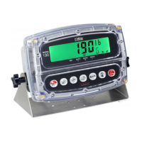
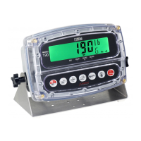
| Model | 190 |
| Category | Measuring Instruments |
| Language | English |