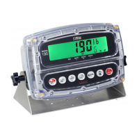
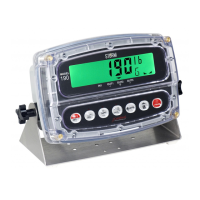
8400-M022-O1 Rev K Model 190 Indicator
Wiring
OUT 1 RED light
OUT 2 GREEN light
The PWC outputs will always function if the indicator is set for d oUt= 5 and AUto=YES.
These outputs can be used, or the serial output of the indicator can contain the light state
information if continuous data type = 2 (tYPE= 2, see below).
tyPE= (Continuous Output Format)
Press the TARE key to show the current setting. If the setting displayed is acceptable,
press the TARE key again to save it.
Otherwise, use the Fn/ key to toggle to a new setting and press the TARE key to save
it. Allowable settings are:
0 = Continuous Output uses SMA format
1 = Continuous Output uses Cardinal Scoreboard format
2 = Continuous Output uses Cardinal SB500 with traffic control format
NOTE: Refer to the CONT1= Continuous Output on Serial Interface, tYPE= parameter
section for a description of output formats 0 and 1.
Cardinal SB500 with traffic control Continuous Output Format
If Cardinal SB500 with traffic control is selected, the data will be transmitted in the following
format:
%NDDDDDDDDDT<CR>
where:
Panel number for a daisy chain configuration
Byte of data to display at a respective location on the scoreboard
T =
Control character for the traffic light. Valid characters for T are:
=
G = Turn on the Green light
R = Turn on the Red light
" "(space) = no lights on