EasyManua.ls Logo

Cardinal 212 Series User Manual

Cardinal 212 Series
154 pages
To Next Page IconTo Next Page
Page #1 background imageLoading...
Page #1 background image
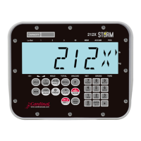
Model 212/212X
Indicator
Installation, Technical
and Operation Manual

Table of Contents

Questions and Answers:

Cardinal 212 Series Specifications

General IconGeneral
BrandCardinal
Model212 Series
CategoryMeasuring Instruments
LanguageEnglish

Summary

Introduction and Important Information

Introduction

Welcome and purpose of the manual for the Cardinal Model 212/212X Weight Indicator.

Copyright and Disclaimer

Legal notices regarding reproduction rights and liability for information use.

General Precautions

Highlights safety warnings and precautions to follow before using the indicator.

Compliance and Disposal

FCC Compliance Statement

Information regarding FCC rules for radio frequency emissions from the equipment.

Proper Disposal Guidelines

Instructions for environmentally responsible disposal of the device at end of life.

1. OVERVIEW

Specifications

Details the technical specifications of the indicator, including power, enclosure, display, and I/O.

Standard Features

Lists the key features and functionalities offered by the indicator.

Options and Accessories

Details available optional hardware, connectivity, and accessories for the indicator.

1.2. Precautions

Static Electricity Precautions

Provides guidelines for handling static-sensitive components to prevent damage.

1.3 Key Descriptions

Keypad Functions Overview

Identifies and explains the primary functions of the indicator's keypad keys.

1.4 Annunciators

Annunciator Descriptions

Explains the meaning and function of each indicator annunciator on the display.

2. GETTING STARTED

Installation Requirements

Covers site prep, environmental needs, electrical power, and transient suppression.

Mounting and Cable Connections

Provides instructions for mounting the indicator and connecting various cables.

DC Power Cable Connection

Explains the wiring for the 2-pin DC power connector.

Scale Cable Connections

Details the wiring for the 5-pin scale connector.

Serial and I/O Cable Connection

Describes connecting serial and I/O cables, including the AGSIO connector.

Internal Components and Jumper Settings

Covers optically isolated I/O, relay boards, main PCB, and jumpers.

2.2. Indicator Setup

Setup Data Entry and Quick Calibration

Guides through data entry and performing a quick calibration of the scale.

Full Setup and Configuration

Details the process for comprehensive setup and configuration of the indicator.

Indicator Settings Configuration

Explains how to configure various settings like domestic/international, units, and intervals.

Calibration Procedures

Describes different calibration modes, including Weigh Bar Table and Load Cell Specs.

Dual-Point Calibration Methods

Explains Dual-Point with Zero and Dual-Point without Zero calibration procedures.

Single-Point Calibration Methods

Details Single-Point for Span Only and Single-Point for Zero Only calibration.

Serial Input/Output Configuration

Serial Port Settings

Configures serial port settings like baud rate, parity, data bits, and stop bits.

Continuous Output Configuration

Configures continuous output for serial ports, including SMA, Cardinal Scoreboard, and SB500 formats.

Print Tab Settings

Defines print settings such as data format, port selection, and time/date location.

Fine Span Adjustment

Guides adjustment of the scale span using test weights.

High Resolution Weight and Key Lock Out

Explains high resolution display and how to lock/unlock keypad keys.

Storing and Restoring Indicator Defaults

Details how to save and restore indicator default settings.

2.3 INDICATOR SETUP REVIEW

Accessing Setup Review

Explains how to access and navigate the indicator setup review menu.

2.4 OPERATIONAL SETUP REVIEW

Accessing Operational Setup Review

Guides on accessing and navigating operational parameters review.

Key Operational Parameters

Lists key operational parameters like D-OUT, FMODE, SPEED, GATE, etc.

3. OPERATION

Standard Weighing

Provides procedures for performing gross and net weight measurements.

Subtractive Weighing

Explains the procedure for subtractive weighing using load and unload modes.

Auto-Hold for Animal Weighing

Details the setup and procedure for weighing animals with auto-hold functionality.

Preset Weight Comparator (PWC)

Describes using presets to compare items against a specified target weight.

Digital Fill Control (DFC) Operations

Explains the Digital Fill Control feature for automated filling operations.

DFC Modes and Setup

Covers Specified Target, Simple, Box-Tracker, and Plot-Tracker DFC modes.

Using Memory/ID Storage

Guides on storing, reviewing, and selecting IDs for weighment data.

4. SERVICE

Troubleshooting Common Issues

Provides solutions for common problems like display issues and incorrect weight.

Error and Status Messages

Lists and explains various error and status messages displayed by the indicator.

4.2 Care and Maintenance

Cleaning and Maintenance Guidelines

Provides guidelines for cleaning and maintaining the indicator.

4.3 Parts Identification

Rear Sub-Assembly Parts

Lists and illustrates the parts for the rear sub-assembly of the indicator.

Front Sub-Assembly Parts

Lists and illustrates the parts for the front sub-assembly of the indicator.

Final Assembly Parts

Lists and illustrates the parts for the final assembly of the indicator.

STATEMENT OF LIMITED WARRANTY

Warranty Terms Summary

Summarizes warranty terms for different product types, including coverage and limitations.

Warranty Limitations and Exclusions

Details limitations, requirements, and exclusions for the product warranty.

Related product manuals